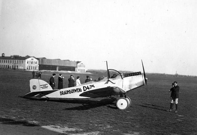
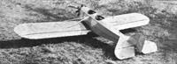
Eine Heinkel HE 18 der technischen Hochschule Braunschweig. Die HE 18 wurde in nur 2 Exemplaren gebaut, eines davon ging an die Flugwissenschaftliche Gruppe der TH Braunschweig (nachzulesen auf dem Leitwerk ). Dort wurde zunächst ein alter Daimler-Vorkriegsmotor mit 70 PS eingebaut, 1925 wurde der Flieger dann auf einen - damals - modernen Junkers L1 mit 80 PS umgerüstet, 1929 ging das Flugzeug zu Bruch.
Die Heinkel HE 18 war eine Weiterentwicklung der HE 3, aber mit Sitzen in Tandem-Anordnung und abgestrebten Tragflächen, diese konnten angeklappt werden
Dieses Flugzeug ist aus der bekannten Göteborger Siegerrnaschine Typ H.E. 3 von 1923 entwickelt. Die bewährte grundkonstruktion ist beibehalten, jedoch wurden fabrikatorische Verbesserungen angewandt, um die für den Serienbau notwendige Verbilligung zu erzielen.
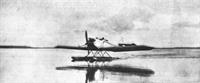
Das Flugzeug ist als Sport- oder Schulflugzeug ausgeführt und kann als Land- oder Wassermaschine geflogen werden. Der Gesamtaufbau der Maschine entspricht in allen
Teilen diesen Zwecken und ist daher besonders klar und einfach gehalten,, um selbst von nicht fachkundigem Personal behandelt werden zu können.
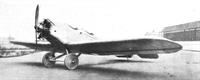
Das Flugzeug ist vom Tiefdeckertyp mit einseitig nach oben ab-gestrebten Flügeln. Die neuesten Forderungen der Aerodynamik wurden bei der Formgebung der Maschine
weitgehendst berücksichtigt. Unter Verwendung nur ebener oder zylindrischer Flächen am Rumpf wird die Fabrikation und infolgedessen auch die Reparaturfähigkeit
bedeutend vereinfacht. Durch Ausschaltung komplizierter Einzelheiten und Vereinfachung in allen Teilen wurde dem Serienbau und somit der Vereinfachung weitgehendst Rechnung getragen. Der gesamte organische Aufbau ist aus diesem Grunde als einfach und zweckmäßig anzusprechen
Der Rumpf des Flugzeuges wird entweder als Stahlrohrrumpf mit Stoffbespannung oder ganz als Holzrumpf mit Fournierbeplankung ausgeführt. Die notwendigen Reparaturen
in Gegenden auszuführen, wo die Herbei Schaffung von Stahlrohrmaterial mit Schwierigkeiten
verbunden ist, machten es notwendig, für diese Zwecke die Ganzholzausführung anzuwenden.Schüler und Lehrer sitzen hintereinander angeordnet. Die Schulsteuerung ist als Knüppelsteuerung ausgeführt, jedoch kann auf Wunsch auch Handradsteuerung eingebaut werden. Um das Flugzeug als Sportmaschine mit Passagier fliegen zu können, ist die vordere Steuerung zum Ausbau eingerichtet. Die Konstruktion ist so durchgebildet, daß der Ausbau der Schulsteuerung ohne Werkzeug durch Lösen eines Schnellverschlusses erfolgen kann. Um Schüler und Führer bei etwaigem Ueberschlag zu schützen, ist über Mitte Rumpf ein von Motorschild bis Hinterkante Lehrersitz reichender Schutzbügel angebracht, der leicht demontierbar ist.
Normalerweise findet der bekannte 70-80 PS Siemens-Stern-Motor Verwendung, der infolge seines günstigen Massenausgleiches einen erschütterungsfreien Lauf
gewährleistet. Es kann jedoch auf Wunsch der 5 Zylinder Siemens-Stern-Motor mit 50-60 PS oder ein anderer gleichwertiger Stand- oder Umlaufmotor (Le Rhone, Gnöme) eingebaut werden. Bei Einbau von Siemens-Stern-Motoren kann gleichzeitig eine elektrische Bosch-Anlaß-Anlage angeschlossen werden. Die Betätigung erfolgt in diesem Falle durch einen Druck auf den Kontaktknopf am Armaturenbrett und das Durchdrehen und Anspringen des Motors erfolgt automatisch.
Unmittelbar hinter dem Motor ist das Brandschott eingebaut. Hinter demselben liegt oben am Rumpf der Benzinfallbehälter. Die Zündmomentverstellung wird direkt am Motor mit dem Gasgestänge so gekuppelt, daß bei Gasgeben die Zündung automatisch mitverstellt wird. Eine besondere Bedienung der Zündverstellung fällt also gänzlich weg.
Diese Bedienung des Motors kann von beiden Sitzen aus erfolgen.
Um eine Einsichtnahme in den Antriebsmechanismus wie Magnete, Vergaser etc. zu ermöglichen, ist der Motor abklappbar eingerichtet und läßt sich nach Lösen von 2 in einer Ebene liegenden Bolzen um eine vertikale Achse drehen. Hierbei sind keinerlei Leitungen zu lösen, da die Benzinzufuhr durch einen Metallschlauch stattfindet. Da der Oeltank sich direkt am Motor befindet, ist ein Lösen der Oel-Ieitung nicht notwendig.
Die Fläche ist normal ausgeführt. Holme und Rippen sind aus amerikanischem Spruce. Als Bespannung wird imprägnierter Spezialstoff verwandt. Querruder sind groß
dimensioniert und werden durch starre Verbindung betätigt. Bei der Flächenkonstruktion ist besonders Wert auf leichte Zugängigkeit und Reparaturfähigkeit gelegt.
Das durchgehende Querruder wird in normaler Weise betätigt und besitzt ferner eine seitlich befindliche Hebelvorrichtung mit Feststellvorrichtung, die ein gleichmäßiges
Herabklappen der beiden Querruder ermöglicht. Zur Verringerung der Landegeschwindigkeit wird die Hebelvorrichtung betätigt, und die Landegeschwindigkeit läßt sich auf diese Art um ca. 12-15% reduzieren. Die Anordnung der Mechanik ist so, daß es selbst bei heruntergeklappten Querrudern möglich ist, vollkommen unabhängig hiervon die Verwinclung mit dem Steuerknüppel zu betätigen.
Durch eine sinnreiche Konstruktion (D. R. P. a.) ist die Möglichkeit gegeben, das Flugzeug in kürzester Zeit derartig zusammenzuklappen, daß einfachste Transport- und
Unterstellmöglichkeit gegeben ist. Die beiden Flächenhälften und Höhenflossen können von einer einzelnen Person demontiert und an den Rumpf angeklappt werden. Die
Betätigung geschieht wie folgt:
1. Anklappell der Höhenflossen mit Höhenruder. Die Abstützungsstrebe der Höhenflosse wird durch Ausheben eine
s selbstsichernden Bolzens am Rumpf gelöst, worauf diese
mit dem Höhenruder hochgeklappt wird und zwar die rechte und linke Flosse je für sich, ohne daß das Steuerkabel gelöst werden muß, da die Verbindung zwischen
Steuerknüppel und Höhenruder eine starre ist.
2. Anklappen der Tragdeckhälften.
Die beiden Tragdeckhälften werden durch je 2 Streben gehalten, die beiderseits am Vorder- und Hinterholm und an einem gemeinsamen Beschlag des oberen Rumpf holm es angreifen. Um das Tragdeck zu demontieren, wird die an dem Vorderholm angreifende Strebe am Tragdeckbeschlag gelöst und an den Rumpf nach vorne angeklappt. Darauf wird der Anschluß des Flächenvorderholms am Rumpf entkuppelt und die Fläche um den Hinterholm gedreht und senkrecht gestellt. Bei diesen Vorgängen ist die Fläche noch durch eine Strebe am Schwerpunkt gehalten und somit derart entlastet, daß die Montage durch eine Person ausgeführt werden kann. In dieser Lage wird sie nach hinten an den Rumpf geschwenkt und mittels einer Arretier-vorrichtung am Rumpf befestigt. In diesem geklappten Zustande nimmt das Flugzeug einen Raum von 7,2 m Länge, 1,9 m Breite und 2,3 m Höhe ein.
Bei dieser Montage ist keine besondere Lösung des Querruder-verbindungsrohres notwendig, da der Eingriff mit dem im Rumpf befindlichen Mechanismus durch eine
Klauenkupplung erfolgt. Die Montage erfolgt sinngemäß in umgekehrter Reihenfolge. Für den ganzen Montagevorgang sind keinerlei Werkzeuge notwendig.
Fahr- und Schwimmergestell sind ohne besondere Hilfsvorrichtungen gegeneinander austauschbar. Das Fahrgestell ist aus Tropfen-Profil Stahlrohr hergestellt. Die Federung
liegt in 2 Federungstöpfen der beiden vorderen Streben.
Das Schwimmergestell besteht aus einem vorderen und hinteren Strebenstück, das in hakenförmige Beschläge der Schwimmer eingreift. Die beiden Schwimmer, die durch einzelne Schotten abgeteilt sind, entsprechen in ihrer Form denen der bekannten und bewährten Hochseeflugzeuge. Die Schwimmer sind nur einmal gestuft, was bei Seegängen das An- und Abwassern erleichtert. Die Montage und Demontage des Schwimmer- und Landfahrgestells erfolgt auch wiederum ohne Hilfswerkzeuge durch selbstsichernde Bolzen.
Die Hauptdaten des Flugzeuges sind, unter Berücksichtigung des «70-80 PS Siemens-Stern-Motors: Nutzlast 220 kg, Vollast 620 kg, Aktionsradius 3 Stunden,
Geschwindigkeit 145 km/Std., Steigzeit 1000 m in 6 Min.
In view of the recent production in this country of a two-seater machine fitted with an engine of 60-70 h.p., and intended for school and sporting flying, i.e. the De Havilland " Moth " with " Cirrus " engine, described and illustrated in FLIGHT of March 5, it is of interest to know what other nations are doing in the matter of machines of approximately this power, and we are, therefore, pleased to be able to place before our readers this week details and illustrations of the new German machine which forms the subject of the following article. Owing to the limitations placed upon the size and power of German aircraft by the Versailles treaty, German designers have for the last few years been turning their attention to machines of a power permitted by the Allies, and have in consequence obtained considerable experience with machines of relatively low power. But for the absence of suitable German small engines it seems likely that more would have been accomplished with really lowpower machines, of the type known in this country as light planes. As it is, most of the German light 'planes have been fitted with British motor-cycle engines. In the lowpower or " not-quite-so-light" plane class, however, the Germans designers have had available for several years engines of suitable type, and most of the German machines are, therefore, fitted with German engines, among which the two types of Siemens radial engines appear to have become most popular.
The Heinkel H.E. 18 shown in the accompanying illustrations was designed by Herr Ernst Heinkel, at one time chief designer to the Caspar works, but now established with his own firm, and constructed by that firm, the Heinkel Flugzeugwerke at Warnemiinde. The machine is the outcome of the Heinkel HE. 3 of 1923, which did so well at Gothenburg, and is very similar to its prototype except in certain minor alterations, made in order to cheapen the machine in quantity production.
Fundamentally the Heinkel H.F..18 is a low-wing monoplane with vee bracing struts as on the De Havilland D.H.53. One objection that has been raised against this type, and the only really serious one we have ever heard put forward, is the possible danger to the crew in case of the machine turning over on the ground. In the Heinkel two-seater provision is made against this by fitting a detachable steel tube guard running from the engine plate to the rear of the aft cockpit. In the photographs this guard is not shown in place, but it is stated that it can be fitted very quickly.
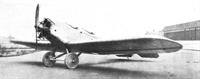
The fuselage is made in two distinct types, according to the requirements of the customer. The standard type, which is the one shown in the photographs, is of steel tube construction and covered with fabric. If, however, the machine is to be used under conditions or in localities where repairs to a steel tubular structure cannot easily be effected, an all-wood fuselage, with ply-wood covering, can be supplied instead.
This question of steel tube construction is one that might, we think, with advantage be taken up again now in this country in connection with low-power aeroplanes. The Fokker form of welded steel tube construction of fuselages is probably the cheapest ever devised, and one very great advantage of it is its adaptability. The change from one shape or size of fuselage to another can be very easily and simply made, and thus the risk of premature standardisation does not arise. Theoretically, it is true, the welded form of construction is open to criticism, but practical experience with the Fokker machines seems to show that the fears of the theorists are not well founded. We do not suggest a slavish copying of Fokker's methods, and would avoid the use of welded joints in tension, but much of the method does appear to be very useful, and it would be interesting to have a ruling from the Air Ministry as regards the application to light 'planes.
However, to return to the " H.E. 18," the two cockpits are arranged in the usual way, the pilot or instructor, as the case may be, occupying the rear cockpit and the passenger or pupil the forward one. Dual controls of the usual " stick " type are provided, but that of the pupil can be removed, without the use of tools, in a few moments. The engine, which is, in the type illustrated, a 7-cylinder
radial air-cooled Siemens rated at 70-80 h.p., but which may be a Siemens 5-cylinder radial of 50 h.p., or any other type desired, is mounted on a swivelling engine plate, which allows of inspecting the back of the engine, with carburettor, magneto, etc., without disconnecting any leads. Aft of the engine is a fireproof bulkhead, and the petrol tank is mounted in the deck fairing aft of this bulkhead, where sufficient head is provided to give direct gravity feed.
The monoplane wings are of normal construction, with spruce spars and ribs, and are chiefly remarkable for the arrangement made for folding. The ailerons run the whole length of the wings, and are stated to give very effective lateral control. By means of a special arrangement the ailerons are also used as variable camber flaps for slow landing, the camber variation being effected by means of a lever in the pilot's cockpit, and the aileron action being retained.
Reference has been made to the wing folding arrangement, which is designed to enable the owner-pilot himself to fold the wings without assistance. The operation consists in folding the two halves of the monoplane wing against the sides of the fuselage, the space in the folded position being further reduced by folding the tail plane against the fin and rudder. The wing-bracing struts are not detached from the fuselage, and in fact the rear strut is not disturbed at all.
The front strut is cast off at the front spar attachment and swung forward against the side of the fuselage, where it is held in position by a clip. The quick-release attachment of the front spar to the fuselage is next released, the wing is swung into a vertical position, leading edge uppermost, and folded along the sides. Doing one side at a time, the pilot can easily fold the wings himself without outside assistance, and the machine can then be stowed in a very small space, or trailed after a motor-car or motor-bicycle.
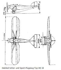
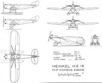
The undercarriage shown in our photographs is of the simple V-type, but in the general arrangement drawings a different form is illustrated, probably with a view to indicate the easy transformation of the machine into a seaplane of the twin-float type. The photograph showing the " H.E.18 " as a seaplane indicates a balanced elevator, so that apparently slightly larger tail surfaces are fitted when the machine is used as a seaplane.
The main dimensions of the Heinkel " H.E.18 " are :
Length, o.a., 7 -20 m. (23 ft. 7 ins.); span, 11.10 m. (36 ft. 5 ins.) total wing area, including ailerons, 188 sq. ft. Weight of machine empty 380 kgs. (836 lb.) ; useful load, 220 kgs. (484 lbs.) ; total loaded weight, 600 kgs. (1,320 lbs.) Maximum speed, 150 km./h. (93-7 m.p.h. ; cruising speed, 140 km./h. (87 m.p.h.). Climb to 1,000 m. in 6 minutes.
No figures are available relating to the landing speed, but in view of the relatively high wing loading this is probably fairly high.
| Type |
Two seat trainer , Land |
Two seat trainer, Seaplane |
| Engine |
1 Junkers L 1b |
1 Siemens Sh 5 or Sh 11 |
| Dimensions |
Length 7,2 m, height 2,7 m, span 11,1 m, wing area 17,4 m2 |
Length 7,8 m, height 3,3 m, span 11,1 m, wing area 17,4 m2 |
| Weights |
Empty 490 kg, flying weight 720 kg |
Empty 545 kg, flying weight 775 kg |
| Performance |
Max. speed 145 km/h, landing speed 78 km/h, climb to 1000 m 9,0 min., service ceiling 3200 m, endurance ca 3 h, range ca 420 km |
Max. speed 140 km/h, landing speed 80 km/h, climb to 1000 m 14,0 min., service ceiling 2500 m, endurance ca 3 h, range ca 420 km |
| Type |
Werk.Nr |
Registration |
History |
|
214 |
D-475 |
Delivered to Flugwissenschaftliche Gruppe der TH Braunschweig. Finished there with a Daimler-Mercedes D 0, later it got a Junkers L 1b . Designated MB 4 . Crashed 18/10 1929 |
|
215 |
D-596 |
Had a Siemens SH 5 engine. Crashed 23/5 1925 |