After the collaboration between the Technical High School Dresden (TH Dresden) and the local flying club, the Flugtechnischer Verein Dresden (F.V.D.), that led to the quite successful 1921 F.V.D. Stehaufchen wing warping biplane glider, the group designed and built a monoplane, the Doris. Originally known as the Dresden Doris or, in the UK at least, as the F.V.D. monoplane, it was later incorporated retrospectively into the Akaflieg Dresden's design list as the D-B2 Doris. Most notably, it had wings which could adjust their relative angles of attack independently both of each other and of the pilot.
The idea of such wings came from the poor understanding of slope soaring in the early 1920s and from observations of bird flight, where wings were seen to twist independently. It was hoped that such freedom could better capture the energy of the gusts that were thought to be the source of slope lift. An early glider of this type had been built by Erich Offermann before World War I and some theoretical work done by Albert Betz and, independently, R. Knoller, began to reach an understanding of how a plunging airfoil could generate thrust (the Knoller-Betz effect). By about 1920 Freidrich Harth was convinced this was essential for extended glider flight and the Harth-Messerschmitt designs were controlled in pitch by a variable angle of incidence wing and roll by wing warping. Its pilot had two levers, one for roll and the other for pitch. The 1921 Loessl Sb.1 Münchener, which won two first and one second prizes at the second Rhön (Wasserkuppe) gliding contest, extended the idea with wings that could be independently rotated with a single, conventional control column, doing away with the wing warping. Ten of the fifty-three competing aircraft at the third Rhön contest, held in 1922, had variable incidence wings but as slope soaring was better understood and the high control forces needed appreciated, rigid wings with ailerons for roll control became standard on gliders.
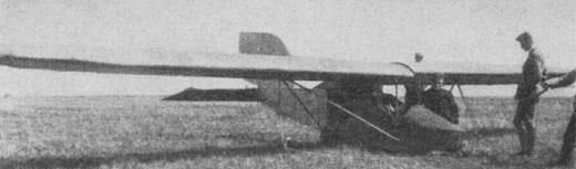
The Doris was a high-wing monoplane using a thick, highly cambered Göttingen 441 airfoil, braced from the lower fuselage on each side by a wide spread inverted V pair of struts connected to the wing at about 30% of the span, immediately below the single main wing spar on which the wing rotated. This was at about 40% chord, where the wing was thickest. The spars were mounted over the fuselage on a narrow central faired column. The wing was largely fabric covered but from the spar forward it was plywood skinned around the leading edge on the upper side, though the ply did not extend as far aft on the underside. The extreme tips were also ply covered.
The fuselage of the Doris had a wooden frame girder structure with a rectangular cross section, tapering aft to a horizontal wedge. Forward of the wing trailing edge it was ply covered, with fabric covering elsewhere. At the nose the sides curved round smoothly and there was also rounded decking immediately ahead of the open cockpit, which was under the leading edge with the vertical front face of the wing support column against the pilot's back. The rear edge of the column dropped gradually away from the trailing edge to the upper fuselage. The angles of incidence were adjusted from the control column via pushrods, sideways movement rotating the wings in opposite directions to roll. Fore and aft movement decreased and increased the angles of incidence together. The intention was that in level flight the pilot should largely allow the wings to follow their optimum setting by themselves. In addition there was a tailplane trim lever, originally fixed to the control column. The high aspect ratio, all-moving tailplane was nearly rectangular in plan apart from angled tips and was fabric covered behind its leading edge. The Doris was a short aircraft and its vertical tail was therefore large, with a quadrant shaped fin and a near rectangular rudder which had a small cut-away at its base for tailplane movement. The vertical tail surfaces were fabric covered. Like the Stehaufchen, the Doris had a pair of horizontal landing skids. These were fixed to the fuselage at the nose and mounted on the ends of a pair of transverse, arched ash brackets on rubber shock absorbers.
The idea of such wings came from the poor understanding of slope soaring in the early 1920s and from observations of bird flight, where wings were seen to twist independently. It was hoped that such freedom could better capture the energy of the gusts that were thought to be the source of slope lift. An early glider of this type had been built by Erich Offermann before World War I and some theoretical work done by Albert Betz and, independently, R. Knoller, began to reach an understanding of how a plunging airfoil could generate thrust (the Knoller-Betz effect). By about 1920 Freidrich Harth was convinced this was essential for extended glider flight and the Harth-Messerschmitt designs were controlled in pitch by a variable angle of incidence wing and roll by wing warping. Its pilot had two levers, one for roll and the other for pitch. The 1921 Loessl Sb.1 Münchener, which won two first and one second prizes at the second Rhön (Wasserkuppe) gliding contest, extended the idea with wings that could be independently rotated with a single, conventional control column, doing away with the wing warping. Ten of the fifty-three competing aircraft at the third Rhön contest, held in 1922, had variable incidence wings but as slope soaring was better understood and the high control forces needed appreciated, rigid wings with ailerons for roll control became standard on gliders.
The Doris was a high-wing monoplane using a thick, highly cambered Göttingen 441 airfoil, braced from the lower fuselage on each side by a wide spread inverted V pair of struts connected to the wing at about 30% of the span, immediately below the single main wing spar on which the wing rotated. This was at about 40% chord, where the wing was thickest. The spars were mounted over the fuselage on a narrow central faired column. The wing was largely fabric covered but from the spar forward it was plywood skinned around the leading edge on the upper side, though the ply did not extend as far aft on the underside. The extreme tips were also ply covered.
The fuselage of the Doris had a wooden frame girder structure with a rectangular cross section, tapering aft to a horizontal wedge. Forward of the wing trailing edge it was ply covered, with fabric covering elsewhere. At the nose the sides curved round smoothly and there was also rounded decking immediately ahead of the open cockpit, which was under the leading edge with the vertical front face of the wing support column against the pilot's back. The rear edge of the column dropped gradually away from the trailing edge to the upper fuselage. The angles of incidence were adjusted from the control column via pushrods, sideways movement rotating the wings in opposite directions to roll. Fore and aft movement decreased and increased the angles of incidence together. The intention was that in level flight the pilot should largely allow the wings to follow their optimum setting by themselves. In addition there was a tailplane trim lever, originally fixed to the control column. The high aspect ratio, all-moving tailplane was nearly rectangular in plan apart from angled tips and was fabric covered behind its leading edge. The Doris was a short aircraft and its vertical tail was therefore large, with a quadrant shaped fin and a near rectangular rudder which had a small cut-away at its base for tailplane movement. The vertical tail surfaces were fabric covered. Like the Stehaufchen, the Doris had a pair of horizontal landing skids. These were fixed to the fuselage at the nose and mounted on the ends of a pair of transverse, arched ash brackets on rubber shock absorbers.
| Type | Single seat glider |
| Dimensions | Length 5,30 m, wingspan 12,20 m, wing area 15,5 m2, aspect ratio 9,5 |
| Weights | Empty 118,5 kg, flying weight 195 kg, wing loading 12,6 kg/m2, wings 55,2 kg, fuselage 45,1 kg, stabilizer 8,2 kg |
| Performance | Max. glide ratio 14,5 |
| Type | Werk.Nr | Registration | History |
| The Doris took part in the 1922 Rhön contest, though Flight noted that it "does not appear to have accomplished very much". It remained on the Wasserkuppe after the competition but crashed, injuring Muttray. The accident, which badly damaged the Doris, was partially ascribed to the unfamiliar control column mounted tailplane trim lever, so when the glider was rebuilt this control was relocated further back in the cockpit. After the rebuild, completed in November 1922, the Doris flew from the Dresden club's airfield at Geising in the Erzgebirge. Some decent but unexceptional flights were made |
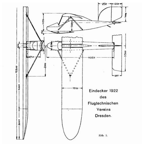
Eindecker 1922 des Flugtechnischen Vereins Dresden.
Von H. Muttray und R. Seiferth,
Die Besprechung des Flugzeuges umfaßt hauptsächlich folgende Punkte: a) Flugeigenschaften, b) Werkstattpraxis, c) Betrieb.
a) Flugeigensehaften. Es wurde angestrebt, mit Hilfe drehbarer Flügel (anpassungsfähige Tragdecks) die Flugeigenschaften zu verbessern. Diesem Gedanken liegt die
bekannte Knoller-Betz'sche Theorie zu Grunde.
Der Anstellwinkel des Tragdecks ist mit Hilfe des Steuerknüppels veränderlich. Die Lage der Flügeldrehachse ist unter Berücksichtigung des Flügelschwerpunktes des
Druckmittelpunktes so gewählt, daß bei normalem Flug keine Kräfte im Steuerknüppel auftreten. Sobald sich dann bei vertikalen Windrichtungsschwankungen die Anblasung
der Tragdeeks ändert, treten infolge der Wanderung des Druckmittelpunktes Kräfte im -Steuerknüppel auf. Der Steuerknüppel bildet also eine Art Böenzeiger. Der Führer hat
den Knüppel entgegen der Kraftrichtung so zu verstellen, daß die Kräfte im Knüppel verschwinden. Dann haben die Tragdecks gegenüber der jeweiligen Anblasung einen
Anstellwinkel, bei dem die günstigsten Verhältnisse von Auftrieb und Widerstand herrschen. Bei etwas gedrücktem Fluge tritt im Knüppel ein gleichmäßiger leichter Zug nach
vorn auf.
Zum Zweck der Höhensteuerung und Verwindung lassen sich die Tragdecks gleichsinnig und gegenläufig verdrehen.
') Da c;, aus 2 Drähten bestehen soll.
-) Es würde It. Tafel 7 auch ein dünnerer Draht genügen, doch seien aus Werkstattrücksichten für die ganze Verspannuug nur zwei verschiedene Drahtstärken ausgeführt.
Die Art der Flügelsteuerung ist die gleiche, wie sie von Lößl und Finsterwalder erstmalig 1921 augewandt hatten. Die Gelenkpunkte des Steuergestänges sind cardanartig
ausgebildet. Der bei der gegenläufigen Verdrehung der Flügel zwischen diesen ' entstehende Schlitz ist durch ein zum Rumpf gehöriges Mittelstück vermieden worden.
Die hinten liegende horizontale Dämpfungsfläche ist mit Hilfe eines verstellbaren Hebels, der sich beim Führersitz befindet, beweglich. Normalerweise wird sie jedoch nicht zur
Höhensteuerung benutzt, da die Flügelsteuerüng wirksam genug ist.
In der ursprünglichen Ausführung in der das Flugzeug beim Rhön-Wettbewerb 1922 erschien, war eine Verstellung der horizontalen Dämpfungsfläche während des Fluges
durch einen beweglichen Handgriff am Steuerknüppel vorgesehen. Es sollte durch die gleichzeitige Bewegung von Flügeln und Dämpfungsfläche eine weitere
Anpassungsfähigkeit des Rumpfes und der Schwanzfläche an die Luftströmung erzielt werden. Aus hier nicht näher anzugebenden Gründen wurde nach dem Rhön Wettbewerb
1922 von dieser Anordnung vorläufig abgesehen. Der Gedanke der gleichzeitigen Bewegung der Flügel und der horizontalen Dämpfungsfläche, der unseres Wissens an
unserem Flugzeug erstmalig ausgeführt wurde, ist damit nicht aufgegeben.
Die Höhensteuerung allein durch die Flügel hat den Vorteil, daß das Trägheitsmoment des Rumpfes in Bezug auf seine Querachse ausgeschaltet ist, denn der Rumpf behält
dauernd ziemlich genau seine Lage bei. Bei der sonst üblichen Höhen Steuerung durch die Schwanzfläche tritt bei jedem Steuerausschlag eine Drehung des Rumpfes um seine
Querachse ein, die auf Kosten der Bewegungsenergie des Flugzeuges geht.
Um den schädlichen Widerstand möglichst klein zu halten, ist für das Tragdeck, das fast freitragend ist, ein gutes Seitenverhältnis gewählt (ungefähr 1 : 9,6). Die Flügelenden
sind zur Verminderung des Randwirbels zugespitzt, und der Flügelquerschnitt gaht außen in ein Tropfenp'rofil mit 0° Anstellwinkel über. Der Rumpfquerschnitt ist möglichst
klein (60 X 70 cm) gehalten. Fahrgestellstreben sind vermieden worden.
b) Werkstattverhältnisse. Der schnellen und billigen Ausführung wegen wurden möglichst einfache Bauelemente in ständiger Wiederholung verwandt. Diese waren
hauptsächlich .Nutengurte mit eingeleimtem Sperrholzsteg und Vierkantenstäbe, die zusammen mit aufgeleimtem und genageltem Sperrholzstreifen U-, T- und Doppel-T-
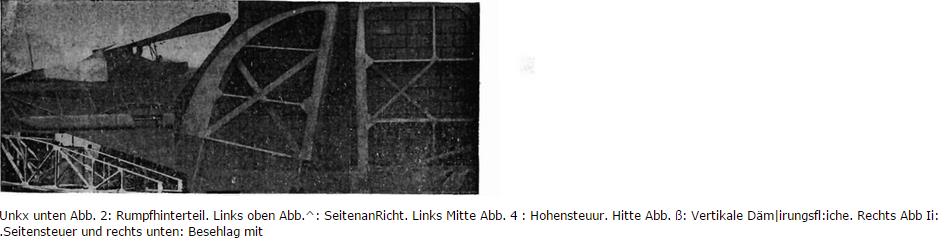
Querschnitte ergaben. Schablonenarheit wurde weitgehend angewendet, z. B. für die Rippen und Rumpfspanten (Abb. 2). Metallteile kamen nur bei "den Beschlägen zur
Aufhängung des Tragdecks in Anwendung.
c) Betrieb. Die Forderungen, die der praktische Betrieb stellt, sind robuste Bauart der beim Landen beanspruchten Teile (Kufen und Rumpfvorderteil), Griffestigkeit aller Teile
für den Transport und einfachster Auf- und Abbau.
Das Rumpfvorderteil, das mit Sperrholz beplankt ist, ist aus starken, mehrfach verleimten Esche-Leisten hergestellt, um bei Stürzen den Führer nach Möglichkeit zu schützen.
Die Kufen liegen dicht unterhalb des Rumpfes und sind gegen diesen durch zwei Bügel abgestützt, die gleichzeitig zur Aufnahme seitlicher Stöße dienen. Kufen und Bügel
bestehen aus mehreren Lagen Esche. Die Abfederung erfolgt durch die Elastizität der Eschekufen
und durch Gummiklötze Diese Bauart wurde schon beim Doppeldecker 1921 des Flugtechnischen Vereins Dresden angewandt, wo sie sich bei den Flügen des Rhön
Wettbewerbes 1921 und 1922 sowie beim Schulbetrieb in Geising i. Erzgebirge 1922 und 1923 ausgezeichnet bewährte.
Der Aufbau des Flugzeuges ist sehr einfach Jeder Flügel ist, abgesehen von der Verbindung mit dem Steuerknüppel, an zwei Punkten, die unter dem Holm liegen, drehbar
aufgehängt. Nach Lösen dieser Verbindung werden die Flügel abgenommen und die Strebendreiecke, die die Flügel halten, an den Rumpf angeklappt. Durch diese Anordnung
ist gleichzeitig eine dauernde genaue Einstellung der Flügel zum Rumpfe erreicht. Für die erstmalig genaue Einstellung sind die aus Stahlrohr bestehenden Streben durch
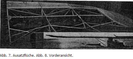
Gewinde in ihrer Länge zu verändern. Die Seitendämpfungsfläche und das Seitensteuer werden nach oben aus dem Rumpf herausgezogen (Abb. 6 u. 7), die Höhensteuerfläche
nach Herausnehmen der Stahlrohrachse abgenommen (Abb. 8). Der Abbau beansprucht etwa 5 Min., der Aufbau 10 Min.
Jeder Flügel besteht aus zwei Teilen: einem inneren Teile von 4 m Länge und einem äußeren Teile von 2 m Länge (Abb. 7), die jedoch lediglich für den Eisenbahntransport
getrennt werden. Der Rumpf ist mit 4,35 m Länge der längste Teil. Das Flugzeug kann also bequem in einem geschlossenen Eisenbahnwagen untergebracht werden.
Der Rumpf des Flugzeuges wurde wie bei dem ebenfalls von uns entworfenen Doppeldecker des F. V. D. von 1921 tiefliegend angeordnet. Diese Anordnung ermöglicht die
Weglassung von Fahrgestellstreben und verhindert infolge der tiefen Schwerpunktslage ein Kippen des Flugzeuges nach der Landung trotz geringer Spurweite der
Fahrgestellkufen. Für den Eindecker (Hochdeckertyp) gestattet diese Rumpfanordnung zudem eine zuverlässige Befestigung der drehbaren Flügel. Der hinter dem Kopf des
Führers liegende Rumpfaufbau ersetzt den Spannturm. Zu beiden Seiten dieses Mittelstückes liegen die Flügel. (Abb. 3 u. 8.)
Der Tragdeckholm ist auf siebenfache Sicherheit berechnet. Er ist als Kastenholm mit innerer Diagonal-Versteifung und ausgesparten Seitenwänden ausgeführt. Zur Erzielung
von Torsionssteifigkeit ist die vordere Hälfte des Profils mit Sperrholz beplankt. Als Flügelquerschnitt wurde Profil 441 der Göttinger Untersuchungen gewählt. Es hat den
Vorteil hoher Auftriebs werte; man kann also hohe Flächenbelastung anwenden und kommt daher mit einer kleinen Tragfläche
Seite S-l
aus. Die Kurve Ca :'/cw- hat ein verhältnismäßig hohes und vor allem breites Maximum, die Sinkgeschwindigkeit ist somit innerhalb eines großen Anstellwinkelbereiches wenig
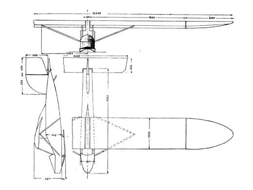
veränderlich. Die Abmessungen des Eindeckers gehen aus der Zeichnung (Abb. 1) hervor. Die Gewichte sind folgende: Zwei Flügel 55,2 kg, Eumpf 45,1 kg, Seitenleitwerk
3,6kg, Höhenstouer 4,ti kg, vier Stahlrohre 10,0 kg, Leergewicht 118,5 kg.
Bei einer Tragfläche von 15,0 in2 erhält man mit 75 kg Führergewicht eine Flächenbelastung von 12,5 kg/m2.
Seit November 1922 ist der Eindecker auf dem Fluggelände des F. V. D. bei Geising im Erzgebirge stationiert. Bei einer Reihe von Flügen, die bei verschiedensten Windstärken
sowie bei Windstille ausgeführt wurden, zeigte der Eindecker sehr gute Flugeigenschaften. Er erwies sich als leicht steuerbar. Der Gleitwinkel wurde bei Windstille zu 1 : 14,0
festgestellt.
Von H. Muttray und R. Seiferth,
Die Besprechung des Flugzeuges umfaßt hauptsächlich folgende Punkte: a) Flugeigenschaften, b) Werkstattpraxis, c) Betrieb.
a) Flugeigensehaften. Es wurde angestrebt, mit Hilfe drehbarer Flügel (anpassungsfähige Tragdecks) die Flugeigenschaften zu verbessern. Diesem Gedanken liegt die
bekannte Knoller-Betz'sche Theorie zu Grunde.
Der Anstellwinkel des Tragdecks ist mit Hilfe des Steuerknüppels veränderlich. Die Lage der Flügeldrehachse ist unter Berücksichtigung des Flügelschwerpunktes des
Druckmittelpunktes so gewählt, daß bei normalem Flug keine Kräfte im Steuerknüppel auftreten. Sobald sich dann bei vertikalen Windrichtungsschwankungen die Anblasung
der Tragdeeks ändert, treten infolge der Wanderung des Druckmittelpunktes Kräfte im -Steuerknüppel auf. Der Steuerknüppel bildet also eine Art Böenzeiger. Der Führer hat
den Knüppel entgegen der Kraftrichtung so zu verstellen, daß die Kräfte im Knüppel verschwinden. Dann haben die Tragdecks gegenüber der jeweiligen Anblasung einen
Anstellwinkel, bei dem die günstigsten Verhältnisse von Auftrieb und Widerstand herrschen. Bei etwas gedrücktem Fluge tritt im Knüppel ein gleichmäßiger leichter Zug nach
vorn auf.
Zum Zweck der Höhensteuerung und Verwindung lassen sich die Tragdecks gleichsinnig und gegenläufig verdrehen.
') Da c;, aus 2 Drähten bestehen soll.
-) Es würde It. Tafel 7 auch ein dünnerer Draht genügen, doch seien aus Werkstattrücksichten für die ganze Verspannuug nur zwei verschiedene Drahtstärken ausgeführt.
Die Art der Flügelsteuerung ist die gleiche, wie sie von Lößl und Finsterwalder erstmalig 1921 augewandt hatten. Die Gelenkpunkte des Steuergestänges sind cardanartig
ausgebildet. Der bei der gegenläufigen Verdrehung der Flügel zwischen diesen ' entstehende Schlitz ist durch ein zum Rumpf gehöriges Mittelstück vermieden worden.
Die hinten liegende horizontale Dämpfungsfläche ist mit Hilfe eines verstellbaren Hebels, der sich beim Führersitz befindet, beweglich. Normalerweise wird sie jedoch nicht zur
Höhensteuerung benutzt, da die Flügelsteuerüng wirksam genug ist.
In der ursprünglichen Ausführung in der das Flugzeug beim Rhön-Wettbewerb 1922 erschien, war eine Verstellung der horizontalen Dämpfungsfläche während des Fluges
durch einen beweglichen Handgriff am Steuerknüppel vorgesehen. Es sollte durch die gleichzeitige Bewegung von Flügeln und Dämpfungsfläche eine weitere
Anpassungsfähigkeit des Rumpfes und der Schwanzfläche an die Luftströmung erzielt werden. Aus hier nicht näher anzugebenden Gründen wurde nach dem Rhön Wettbewerb
1922 von dieser Anordnung vorläufig abgesehen. Der Gedanke der gleichzeitigen Bewegung der Flügel und der horizontalen Dämpfungsfläche, der unseres Wissens an
unserem Flugzeug erstmalig ausgeführt wurde, ist damit nicht aufgegeben.
Die Höhensteuerung allein durch die Flügel hat den Vorteil, daß das Trägheitsmoment des Rumpfes in Bezug auf seine Querachse ausgeschaltet ist, denn der Rumpf behält
dauernd ziemlich genau seine Lage bei. Bei der sonst üblichen Höhen Steuerung durch die Schwanzfläche tritt bei jedem Steuerausschlag eine Drehung des Rumpfes um seine
Querachse ein, die auf Kosten der Bewegungsenergie des Flugzeuges geht.
Um den schädlichen Widerstand möglichst klein zu halten, ist für das Tragdeck, das fast freitragend ist, ein gutes Seitenverhältnis gewählt (ungefähr 1 : 9,6). Die Flügelenden
sind zur Verminderung des Randwirbels zugespitzt, und der Flügelquerschnitt gaht außen in ein Tropfenp'rofil mit 0° Anstellwinkel über. Der Rumpfquerschnitt ist möglichst
klein (60 X 70 cm) gehalten. Fahrgestellstreben sind vermieden worden.
b) Werkstattverhältnisse. Der schnellen und billigen Ausführung wegen wurden möglichst einfache Bauelemente in ständiger Wiederholung verwandt. Diese waren
hauptsächlich .Nutengurte mit eingeleimtem Sperrholzsteg und Vierkantenstäbe, die zusammen mit aufgeleimtem und genageltem Sperrholzstreifen U-, T- und Doppel-T-
Querschnitte ergaben. Schablonenarheit wurde weitgehend angewendet, z. B. für die Rippen und Rumpfspanten (Abb. 2). Metallteile kamen nur bei "den Beschlägen zur
Aufhängung des Tragdecks in Anwendung.
c) Betrieb. Die Forderungen, die der praktische Betrieb stellt, sind robuste Bauart der beim Landen beanspruchten Teile (Kufen und Rumpfvorderteil), Griffestigkeit aller Teile
für den Transport und einfachster Auf- und Abbau.
Das Rumpfvorderteil, das mit Sperrholz beplankt ist, ist aus starken, mehrfach verleimten Esche-Leisten hergestellt, um bei Stürzen den Führer nach Möglichkeit zu schützen.
Die Kufen liegen dicht unterhalb des Rumpfes und sind gegen diesen durch zwei Bügel abgestützt, die gleichzeitig zur Aufnahme seitlicher Stöße dienen. Kufen und Bügel
bestehen aus mehreren Lagen Esche. Die Abfederung erfolgt durch die Elastizität der Eschekufen
und durch Gummiklötze Diese Bauart wurde schon beim Doppeldecker 1921 des Flugtechnischen Vereins Dresden angewandt, wo sie sich bei den Flügen des Rhön
Wettbewerbes 1921 und 1922 sowie beim Schulbetrieb in Geising i. Erzgebirge 1922 und 1923 ausgezeichnet bewährte.
Der Aufbau des Flugzeuges ist sehr einfach Jeder Flügel ist, abgesehen von der Verbindung mit dem Steuerknüppel, an zwei Punkten, die unter dem Holm liegen, drehbar
aufgehängt. Nach Lösen dieser Verbindung werden die Flügel abgenommen und die Strebendreiecke, die die Flügel halten, an den Rumpf angeklappt. Durch diese Anordnung
ist gleichzeitig eine dauernde genaue Einstellung der Flügel zum Rumpfe erreicht. Für die erstmalig genaue Einstellung sind die aus Stahlrohr bestehenden Streben durch
Gewinde in ihrer Länge zu verändern. Die Seitendämpfungsfläche und das Seitensteuer werden nach oben aus dem Rumpf herausgezogen (Abb. 6 u. 7), die Höhensteuerfläche
nach Herausnehmen der Stahlrohrachse abgenommen (Abb. 8). Der Abbau beansprucht etwa 5 Min., der Aufbau 10 Min.
Jeder Flügel besteht aus zwei Teilen: einem inneren Teile von 4 m Länge und einem äußeren Teile von 2 m Länge (Abb. 7), die jedoch lediglich für den Eisenbahntransport
getrennt werden. Der Rumpf ist mit 4,35 m Länge der längste Teil. Das Flugzeug kann also bequem in einem geschlossenen Eisenbahnwagen untergebracht werden.
Der Rumpf des Flugzeuges wurde wie bei dem ebenfalls von uns entworfenen Doppeldecker des F. V. D. von 1921 tiefliegend angeordnet. Diese Anordnung ermöglicht die
Weglassung von Fahrgestellstreben und verhindert infolge der tiefen Schwerpunktslage ein Kippen des Flugzeuges nach der Landung trotz geringer Spurweite der
Fahrgestellkufen. Für den Eindecker (Hochdeckertyp) gestattet diese Rumpfanordnung zudem eine zuverlässige Befestigung der drehbaren Flügel. Der hinter dem Kopf des
Führers liegende Rumpfaufbau ersetzt den Spannturm. Zu beiden Seiten dieses Mittelstückes liegen die Flügel. (Abb. 3 u. 8.)
Der Tragdeckholm ist auf siebenfache Sicherheit berechnet. Er ist als Kastenholm mit innerer Diagonal-Versteifung und ausgesparten Seitenwänden ausgeführt. Zur Erzielung
von Torsionssteifigkeit ist die vordere Hälfte des Profils mit Sperrholz beplankt. Als Flügelquerschnitt wurde Profil 441 der Göttinger Untersuchungen gewählt. Es hat den
Vorteil hoher Auftriebs werte; man kann also hohe Flächenbelastung anwenden und kommt daher mit einer kleinen Tragfläche
Seite S-l
aus. Die Kurve Ca :'/cw- hat ein verhältnismäßig hohes und vor allem breites Maximum, die Sinkgeschwindigkeit ist somit innerhalb eines großen Anstellwinkelbereiches wenig
veränderlich. Die Abmessungen des Eindeckers gehen aus der Zeichnung (Abb. 1) hervor. Die Gewichte sind folgende: Zwei Flügel 55,2 kg, Eumpf 45,1 kg, Seitenleitwerk
3,6kg, Höhenstouer 4,ti kg, vier Stahlrohre 10,0 kg, Leergewicht 118,5 kg.
Bei einer Tragfläche von 15,0 in2 erhält man mit 75 kg Führergewicht eine Flächenbelastung von 12,5 kg/m2.
Seit November 1922 ist der Eindecker auf dem Fluggelände des F. V. D. bei Geising im Erzgebirge stationiert. Bei einer Reihe von Flügen, die bei verschiedensten Windstärken
sowie bei Windstille ausgeführt wurden, zeigte der Eindecker sehr gute Flugeigenschaften. Er erwies sich als leicht steuerbar. Der Gleitwinkel wurde bei Windstille zu 1 : 14,0
festgestellt.