| Type |
Two seat sportplane |
| Engine |
1 Bristol Lucifer |
| Dimensions |
Length , height , span , wing area , |
| Weights |
Empty , loaded 825 kg , max. take off weight |
| Performance |
Max.. speed 150 km/h , cruising speed , range , endurance , service ceiling , climb |
| Type |
Werk.Nr |
Registration |
History |
|
|
D-674 |
Took part in the Deutschen Rundflug 1925 |
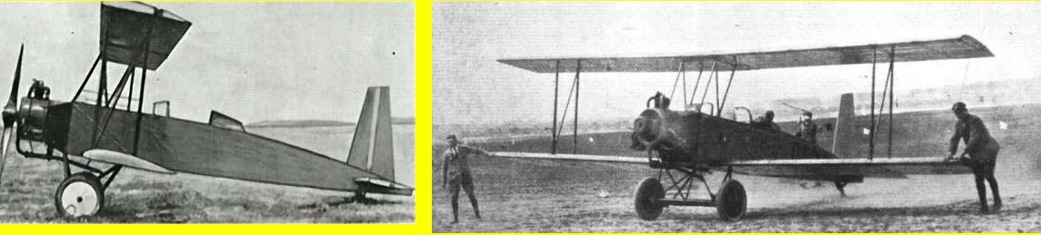
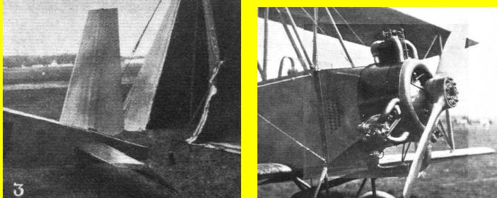
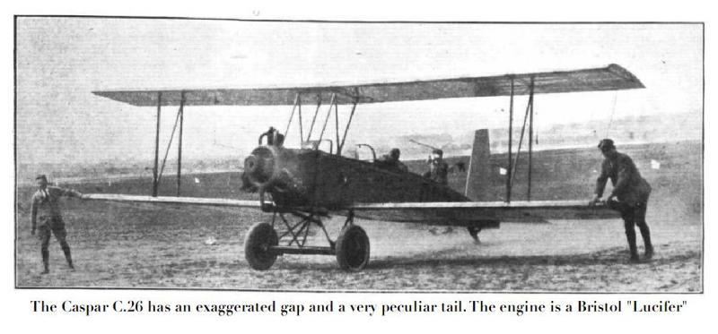
Typ C 26 besitzt 100 PS Bristol „Lucifer'-Motor und ist für Schul-und Uebungszwecke sowie für Kunstflug geeignet. Die Sicherheit ist bei allen drei Typen außergewöhnlich hoch gewählt, trotzdem aber durch Reduzierung überflüssiger Konstruktionselemente ein normales Leergewicht erreicht. Infolge der verschiedenen Motorgwichte ist die A-Fall-Sicherheit bei Typ C 23 zehnfach, bei Typ C24 8,5fach, bei Typ C26 llfach. Es wurden Bruchproben angestellt und bei Belastung eines kompletten Flügels mit Verspan-nung und Anschlußbeschlägen bei 9facher Sicherheit von Typ C24 im A-Fall noch kein Bruch erreicht.
Die Zelle besteht aus 4 gleich großen Flächen, dem senkrechten Baldachin, 2 N-Stielen und je Seite 2 Trag- und 1 Gegenkabel. Die Flächen sind zweiholmig ausgeführt und
besitzen je nur 7 gleiche Rippen. Alle Rippen, mit Ausnahme der Endrippe, sind offen ausgeführt, so daß die Flächen nach harten Landungen von der Innenrippe aus mittels der
Ausleuchtlampe innen kontrolliert werden können. Die Beplankung besteht aus Sperrholz. Das Flügelgerippe wird nur aus den beiden Holmen, einem einfachen inneren
Rohrfachwerk zur Aufnahme der Widerstände und der Holmverdrehung und den 7 Rippen aufgebaut. Die Querversteifungen der Beplankung zwischen den Rippen werden mit
der Beplankung aufgebracht. Der so gebaute Flügel ist außerordentlich leicht reparaturfähig. Die Querruder befinden sich im Oberflügel.
Der Rumpf besteht aus drei Hauptteilen, der Motorbrücke, dem Stahlrohrchassis und dem Holzrumpf. Die Motorbrücke aus Stahlrohr ist mit 4 Bolzen an das Stahlrohrchassis
angeschlossen. Der Motor kann mitsamt Kühler und allen Verkleidungen durch Lösen von 4 Muttern vom Rumpf abgenommen werden.
Das Stahlrohrchassis nimmt die beiden Sitze auf sowie alle Einbauten der Steuerung. Diese besteht aus einer horizontalen Längswelle, welche an ihrem vorderen bezw.
hinteren Ende die beiden Steuerknüppel für Führer und Schüler trägt. Die Seitenruderhebel sind gesondert gelagert. Die Höhenruderbetätigung erfolgt vom hinteren Knüppel aus durch gerade durchlaufende Seile, der vordere und hintere Knüppel ist durch eine Stange gekuppelt. Die Querruderbetätigung erfolgt durch Seilzüge über Umleitrollen, ebenso die Seiten-ruderbedienung. Die Fußböden bestehen aus herausnehmbaren hölzernen Rosten, welche sich auf die unteren Längsrohre des Chassis auflegen.
Der Holzrumpf ist mit den 4 Holmen durch äußerst kräftige Knotenpunktverbindungen an das Stahlrohrchassis gekuppelt. Sämtliche Rumpfspanten bestehen aus gleichen Profil leisten, welche viereckige Rahmen bilden. Aehnlkh der Flächenherstellung werden auch hier die Spanten nicht auf einer Helling errichtet, sondern in ihren Einzelteilen aufdie Sperrholz-beplankung aufgebracht und mit dieser zusammen an den Holmen befestigt und sodann an den Ecken verlascht.
Das Rumpfende ist durch einen kräftigen Spant aus Ovalrohr abgeschlossen, welcher das Höhen- und Seitenleitwerk sowie den Sporn mit seiner Abfederung trägt. Durch
Lösen der kurzen Abschlußhaube sind diese Teile sofort einzusehen. Das Höhenleitwerk besteht aus einer durchgehenden Dämpfungsfläche und einem durchgehenden
Höhenruder. Das Höhenruder ist dreifach gelagert. In gleicher Weise ist das Kursleitwerk aufgebaut. Auch das Leitwerk besitzt Sperrholzbeplankung und gleicht im Aufbau
den Flügeln.
Das Fahrgestell ist aus 2 seitlichen N-Stielen, einem vorderen M-Spant, 2 Hilfsachsen mit unterer Scherplatte und Aluminiumverkleidung gebildet. Der Abstand der Hilfsachsen
ist sehr groß gewählt, so daß die Radachse auch noch vorn und rückwärts schwingen kann. Die Gummiseile liegen im Normalzustand sehr flach und stellen sich erst bei
stärkerer Durchfederung senkrecht, so daß eine Differentialfederung entsteht, welche sehr weich anspricht, aber auch schwere Stöße aufzunehmen vermag. Durch diese
Anordnung zusammen mit dem großen Hilfsachsenabstand wird Start und Landung bei schlechtestem Boden ermöglicht bezw. kurzer Start ohne Springen des Flugzeuges
erzielt. Die Räder in der Größe von 700X100 sind ebenfalls zur leichten Ausführbarkeit von Außenlandungen überdimensioniert.
Besonderer Wert wurde mit Rücksicht auf Ueberschläge, wie sie sich im Schulbetriebe ereignen können, auf Feuersicherheit gelegt. Das Benzin für 2% Stunden Flug ist
ausschließlich in einem Fallbehälter im Baldachin untergebracht, welcher mit einem Gummiüberzug versehen ist. Die Fällbenzinleitung ist offen verlegt und durch leicht
erreichbaren Absperrhahn zu schließen. Die Vergaser sind in eine feuersichere Stahlkammer eingebaut. Hinter dem Motor befindet sich ein Feuerschott, bestehend aus 2
Stahlblechwänden in 30 mm Abstand mit Luftraum dazwischen. Das ganze Rumpfvorderteil bis zum Führersitz besteht nur aus Stahl und Aluminium. Ebensogroßer Wert ist
auf die Sicherheit gegen Verletzung bei Bruchlandungen gelegt. Beide Insassen sind vor Holzsplittern dadurch vollkommen sicher, daß sie in dem stark überdimensionierten
Stahlrohrchassis sitzen, welches auch bei schwerem Bruch nicht eingedrückt wird. Führer- und Schülerraum sind durch Moosgummi stark gepolstert. Jede Möglichkeit des
Hängenbleibens an vorstehenden Teilen ist ausgeschaltet. Die Vorderkante des Schüler- und Führerraumausschnittes sowie der Windschirme ist stark gummiarmiert. Vor der
Brust beider Insassen ist ein nachgiebiger Gummiriemen quer durch den Rumpf gespannt.
Besonderer Wert wurde auf leichte Auf- und Abrüstbarkeit bezw. auf gute Austauschbarkeit aller Teile gelegt. So kann von dem dreiteilig gebauten Rumpf der jeweils
beschädigte Teil entfernt und der übrige Rumpf weiter verwendet werden, Bei einem Kopfstand mit Bruch der Schraube und des Rumpfvorderteiles kann beispielsweise durch
Lösen der ganzen Motorbrücke das Flugzeug innerhalb v2 Stunde wieder flugfähig sein. Bei Abrutschen auf dem Flügel wird häufig durch Ausreißen der Anschlußbeschläge das
Rumpf mittel stück beschädigt sein; es kann durch Abkuppeln der Motorbrücke und des Holzrumpfes ebenfalls in Kürze durch ein neues ersetzt werden. Bei Abrutschen nach
rückwärts kann das Leitwerk mit dem Holzrumpf ausgetauscht werden usw. Um das Flugzeug nach harten Landungen leicht in allen Teilen auf seinen Zustand kontrollieren zu
können, wurde jeder Beschlag bezw. jeder vitale Punkt ohne gewaltsames Entfernen von Beplankungen und Verkleidungen zugängig gemacht. So ist die Motorbrücke durch
Oeffnen der großen Seitentür sofort vollkommen freizulegen. Das Chassis kann vom Führer- und Schüler sitz aus in jedem Punkt eingesehen werden. Die Leitwerkbefestigung
ist durch Entfernen der Endhaube zu kontrollieren, das Innere der Leitwerkflächen durch Ausleuchten von den Innenrippen aus genau wie bei den Flügeln usw.







