| Type |
Two seat sportplane |
| Engine |
1 Daimler D I |
| Dimensions |
Length 7,0 m , height , span 11,5 m , wing area , |
| Weights |
Empty 625 kg, loaded 860 kg , max. take off weight |
| Performance |
Max.. speed 150 km/h , cruising speed , range , endurance , service ceiling , climb |
| Type |
Werk.Nr |
Registration |
History |
|
|
D-673 |
|
|
|
D-683 |
|
|
5017 |
D-976 |
Daimler I. To Aero-Express, Leipzig in April 1928, to DVS GmbH in Nov. 1928. Dismantled in June 1929 |
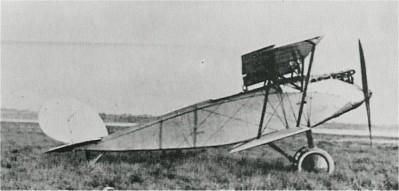
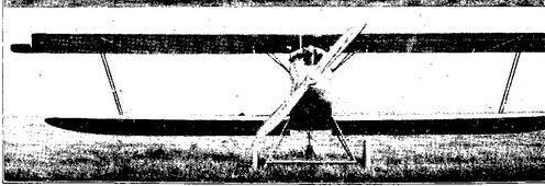
Die Typen Caspar-Theis CT 1, CT 2, CT 4, CT 5
sind in Aufbau und Konstruktion gleich und unterscheiden sich nur geringfügig voneinander. Die Unterschiede bestehen im Einbau von 80 PS Mercedes bei CT 1, 100 PS
Mercedes bei CT 2 und CT 5, 120 PS Mercedes bei CT 4.
Die Type CT 4 besitzt gegenüber den anderen Typen einen gemeinsamen Rumpf ausschnitt für Führer und Beobachter. Die Type CT 5 ist als Schulmaschine mit Schulsteuerung
eingerichtet. Die Berechnung des Tragdecks usw. ist nach den bestehenden Vorschriften vorgenommen und durch Belastungsprüfungen bestätigt worden.
Die Spannweite des Oberdecks beträgt 11,5 m, die des Unterdecks 9 m und die Flächentiefe oben und unten 1,4 m. Das Oberdeck ist gegen das Unterdeck nach vorne
gestaffelt und besitzt über dem Fluggastsitz einen kreisförmigen Ausschnitt. Die Gesamttragfläche ist 25 m2. Das Leergewicht beträgt 600 kg, die Zuladung 260 kg und das
Fluggewicht 860 kg, die spez. Flächenbelastung demzufolge 34,4 kg.
Die Maschinen sind als einstielige Doppeldecker mit normaler Ver-spannung ausgeführt. Die Unterdecks sind an den Rumpf angelenkt. Die Oberdecks sind an dem vom
Baldachin getragenen Mitteldeck befestigt. Der Baldachin hat N-Form und besteht aus tropfenförmigem Stahlrohr. Er ist von vorn und hinten durch je ein Kabel zur
Rumpf unterkante abgefangen.
Der Stiel besteht aus zwei Streben und zwei diagonalen Auskreuzungskabeln. Das Mitteldeck nimmt in der Mitte den Tragdeck-Kühler auf, und seitlich von diesem ist ein
Falltank eingebaut. Die Flügel sind in normaler Bauart zweiholmig mit Stoffbespannung und Kabelauskreuzung ausgeführt. Die Holme sind aus dem vollen auf doppelt T-förmi-
gen Querschnitt ausgefräst. Die Hinterholme sind nach dem Ausfräsen beiderseits mit Sperrholz beplankt worden. Die Rippenkonstruktion besteht aus Nutengurten mit
Sperrholzstegen und fachwerk-artig angeordneten Holzleisten. Die Rippen sind von innen bis fast ganz nach außen mit gleichbleibendem Profil, nur die Endrippen mit
abnehmendem Profil ausgeführt. Die Abschlußleiste besitzt runde Form und ist hohl ausgekehlt.
Der Rumpf ist vierholmig aus normaler Schottkonstruktion und Sperrholzbeplankung aufgebaut und läuft in eine horizontale Schneide aus. Die Dämpfungsfläche und die
Kielfläche haben ebenfalls wie die Flügel normale Holzholme und Rippenkonstruktion. Der Sporn ist an einen Spornbock aus Stahlrohr und mit Gummizügen abgefedert.
Die Steuerflächen und Verwindungsklappen sind aus Stahlrohr mit Stoffbespannung hergestellt. Die Betätigung des Höhen- und Seiten-
ruders erfolgt durch Seilzüge. Die Verwindungsklappen werden von der Steuerwelle im Rumpf mittels Querhebel, Stoßstangen, die an, durch den ganzen Flügel laufenden
Querruderwellen befestigten Hebeln angreifen, betätigt.
Das Fahrgestell besteht aus zwei V-Streben, die unten durch zwei Hilfsachsen verbunden sind. Die vordere und hintere Strebenebene ist durch Stahlkabel ausgekreuzt. Die
Hauptachse ist in Gummizügen federnd aufgehängt. Der Federungsweg ist durch ein Abfangkabel begrenzt. Der Motorraum ist von dem dahinterliegenden Haupttank durch
eine Stahlblechschottwand feuersicher getrennt.