Heinkel-Ampfibium H. E. 57. (FLUGSPORT)
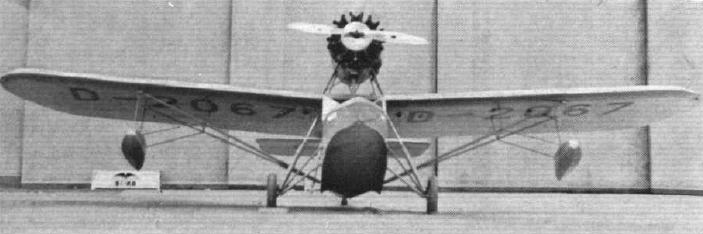
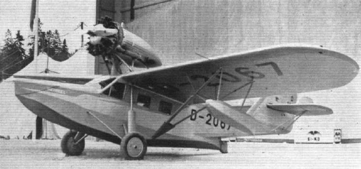
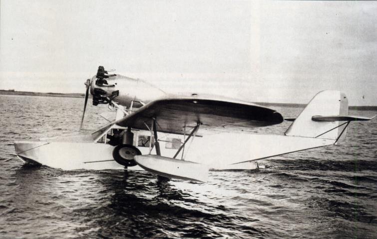
Das als Kabinenflugzeug zur Gastbeförderung gebaute Flugzeug Typ Heinkel H. E. 57 , ausgerüstet mit einem über dem Rumpf angeordneten 425-PS-Wasp-Motor, ist ein Boots-Amphibium mit seitlichen Stützschwimmern. Die in Hochdeckeranordnung angesetzten Flügel sind im äußeren Drittel abgestrebt, das hochziehbare Fahrgestell ist in je drei Punkten am Boot gelagert und das Leitwerk in üblicher Weise am Rumpfende befestigt.
Die gesamte Zelle ist in ihren lebenswichtigen Teilen vorwiegend aus Leichtmetall hergestellt, einige hochbeanspruchte Teile sind aus Stahl. Abgesehen von der
Stoffbespannung des Flügels und des Leitwerks sind als einzige nicht metallene Teile nur die Flügelholme aus Holz angefertigt. Die Baudurchführung entspricht den
Vorschriften der Deutschen Versuchsanstalt für Luftfahrt e. V., Berlin-Adlershof, sowie den Zulassungsbestimmungen für Verkehrsflugzeuge in U. S. A.
Der Bootskörper ist durch wasserdichte Schotten in drei Abteilungen eingeteilt.
Die mittlere Abteilung bildet die Kabine, zu welcher man durch eine auf dem hinteren Deck befindliche Tür über eine Treppe gelangt. Die Kabine enthält drei Paar
hintereinander!legende Sitze, von denen die beiden vorderen mit Steuerung, ausgerüstet sind. Ein bequemer Längsgang zwischen den Sesseln ermöglicht den Durchgang zum Bug-und Heckraum. Im hinteren Teil der Kabine neben der Treppe befindet sich der Waschraum mit Toilette. Unter der Treppe ist Platz für Gepäck.
Der Bugraum dient zur Unterbringung der See-Ausrüstung und des Gepäcks und ist von außen durch eine im Oberdeck befindliche Luke betretbar, von der Kabine aus
durch eine wasserdichte Schotttür.
In den Heckraum gelangt man zur Kontrolle der Steuerung und Konservierung des Bootsinnern — von der Kabine aus durch eine im Schott befindliche Luke.
Das im Querschnitt rechteckige Boot ist ein Einstufenboot, vorn und hinten gekielt. Zur Anbringung des Wasserruders besitzt der Bootsboden hinter der Stufe einen in der Draufsicht V-förmigen Ansatz. Der konstruktive Aufbau des Bootes erfolgt durch Querspanten, welche durch vier Längsträger und durch die glatte Außenhaut verbunden sind. Der Boden ist durch ein Kielprofil, welches als Scheuerleiste ausgebildet ist, verstärkt.
Besonderer Wert ist auf einwandfreie Konservierung sämtlicher Profile und der innenliegenden Metallteile gelegt.
Zur Entwässerung des Bootsinnern ist eine Lenzanlage mit Leitungen nach allen drei Abteilungen eingebaut. Die zugehörige Lenzpumpe mit Verteilerhahn befindet sich neben der Treppe.
Die Führersitze sind mit splitterfreien Glasscheiben abgedeckt, welche auch bei der Landung gute Sicht nach vorn, unten und der Seite gewähren. Für die Sicht nach
hinten oben befindet sich im Deck ein Zellonfenster. Die Fenster neben den Führersitzen können geöffnet werden und sind so groß, daß sie als Notausgang benutzt werden können. Die vier hinteren Sitze haben an der
Bootsseite je ein ca. 350X500 mm großes Fenster aus splitterfreiem Glas.
Am Bug befindet sich der Bugfender, der Schleppschäkel und eine Klampe. Der vordere Lukdeckel ist nach hinten bis etwa 135 Grad klappbar, so daß er bei der Arbeit am Bug Schutz gegen den laufenden Propeller bietet.
Das Oberdeck ist vorn bis zum hinteren Einstieg begehbar. Sämtliche Befestigungsbeschläge für Flügel-, Leitwerk-, Sport-, Wasserruder- und Motorstützgestell-Anschluß sind so konstruiert, daß sie gut üben/acht werden können. Für das Heißen des Flugzeuges sind entsprechende Aufhänge-Beschläge vorgesehen. An der Bootsseite in der Nähe des hinteren Einstiegs befinden sich Aufstiege.
Die Flügel besitzen Kastenholme, bei denen die Gurte aus Spruce, die Stege aus Birkensperrholz hergestellt sind. Die innere Verspan-nung besteht aus Leichtmetall und Stahlrohren im Diagonal-Verband. Die Stoffbespannung ist in besonderer Weise mittels durch Oesen gezogenem Draht an den aus Metall hergestellten Rippen befestigt.
Die V-förmige Strebenabstützung nach dem Boot bestellt aus tropfenförmig verkleideten Sthalrohren mit Verstell köpfen. Die V-Stellung der Flügel beträgt ca. ZV2 Grad.
Im Flügel zwischen den Holmen ist die Lagerung für die Brennstofftanks, in der Nase die Unterbringung des Werkzeugkastens vorgesehen.
Die Stützschwimmer sind aus Leichtmetall, die Streben und Beschläge aus Stahl. Dei Schwimmer sind in drei wasserdichte Abteilungen geteilt, welche zu Kontroll- und
Konservierungszwecken mit Hand lochdeck ein versehen sind.
Die stoöbespannte Seiten- und Höhenflosse besteht aus zwei Holmen mit zwischengesetzten Rippen aus Leichtmetall und der Diagonalauskreuzung. Die Seitenflosse ist mit vier Bolzen auf dem Rumpf aufgeschraubt, während die im Fluge verstellbare Höhenflosse in halber Höhe der Seitenflosse durch diese hindurchgesteckt und gelagert und halbfreitragend mittels V-Strebe nach dem Rumpf abgestützt ist.
Sämtliche Ruder (Seitenruder, Höhenruder und Querruder) sind stoffbespannt und bestehen aus dem Ruderholm (aus Leichtmetall oder Stahlrohr) und den
übergeschobenen Rippen. Höhen- und Seitenruder sind nicht entlastet. Die Querruder sind durch ihre Formgebung ausgeglichen.
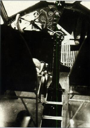
Die Steuersäule, welche Höhen- und Quersteuerung über Handrad, Segment und Kabel betätigt, ist in Bootsmitte gelagert. Ein das Handrad tragender Arm ist
schwenkbar an der Steuersäule angeordnet, so daß das Handrad von beiden Führersitzen aus bedient werden kann.
Die Seitensteuerung erfolgt durch verstellbare Pedale über Kabel. Für den zweiten Führer sind im Bedarfsfalle einsteckbare Fußhebel vorhanden.
Die Umlenkung sämtlicher Steuerkabel erfolgt über kugelgelagerte Rollen. Die Kabel laufen innerhalb der Kabine unter dem Mittelgang des Fußbodens, außerhalb der
Kabine über das Oberdeck bzw. in den Flächen. Sämtliche Steuerzüge sind leicht zu kontrollieren. Die Höhenflossen Verstellung geschieht mittels Handrad vom Führersitz aus über Kabel und Spindel. Die Seitenruderkabel sind über zwischengeschaltete Federn mit dem am Bootsansatz gelagerten Wasserruder gekuppelt. Das Wasserruder ist als Sporn ausgebildet.
Das Fahrgestell ist in je drei Punkten am Boot gelagert und besteht aus Achse, Zugstrebe, der Druckstrebe mit OelStoßdämpfer und bremsbaren Rädern. Sämtliche
Fahrgestellstreben bestehen aus Stahlrohren und sind windschnittig verkleidet. Die Bremsung der Bendix-Räder erfolgt vom Führersitz aus durch Bewegung der
Seitensteuer-Fußhebel um die Horizontalachse.
Die Hochzieh Vorrichtung des Fahrgestells kann auf Wunsch hydraulisch oder mechanisch ausgeführt Vierden. Die Betätigung erfolgt in beiden Fällen vom Führersitz aus.
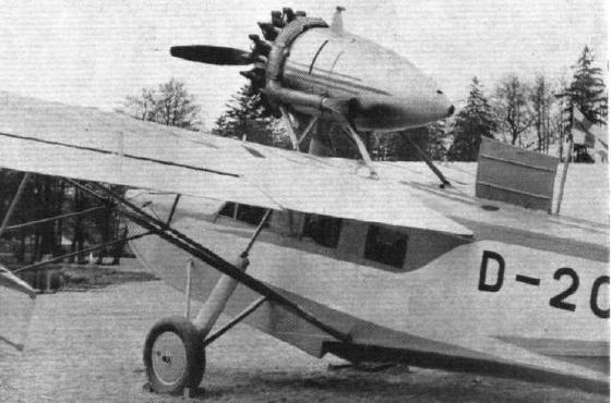
Der 425-PS-Wasp-Motor ist über dem Boot auf einem aus Stahlrohr geschweißten Stützgestell, welches mit vier Bolzen am Boot befestigt ist, gelagert. Er kann ohne
Umkonstruktion durch einen 525-PS-Hornet-Motor ersetzt werden. Die Zugschraube aus Metall bewegt sich im vorgeschriebenen Abstand von den Führern und den
lebenswichtigen Steuerteilen. Die Motorsteuerung erfolgt mittels Gestänge unter Verwendung von biegsamen Umlenkungen, Eine leicht abnehmbare tropfenförmige
Verkleidung gibt dem Motor gute aerodynamische Form. Der konische Hinterteil der Verkleidung ist als Oel- und Zusatz-Benzintank ausgebildet, welcher durch ein
Brandschott nach vorn abgetrennt ist. Die Speisung des Motors erfolgt aus den beiden im Flügel gelagerten Hauptbenzintanks mittels motorgetriebener Pumpen.
Die Kabine mit 6 bequemen Sesseln ist geschmackvoll mit bestem Kordstoff ausgekleidet und mit dunkelfarbigem Boucle-Teppich belegt.
Die Sitzkissen der Sessel enthalten die Kapok Schwimmwesten. Die Führersessel sind in der Höhe verstellbar.
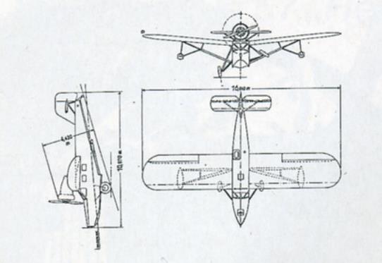
Spannweite 16,00 m, Länge 10,80 m, Höhe 3,55 m, Höhe mit Fahrgestell 4,23 m, aerodynamische Fläche 39,20 m2, Leergewicht 1625 kg, Zuladung 825 kg, Fluggewicht 2450 kg; Zuladung: 6 Personen 460 kg, Betriebsstoff 305 kg, Gepäck 60 kg, zusammen 825 kg; Max.-Geschwindigkeit in Seehöhe 180 km/h, Landegeschwindigkeit 95 km/h, Steigzeit auf 1000 m 6,9 Min,, auf 2000 m 15,9 Min.; Flächenbelastung 62,5 kg/m2, Leistungsbelastung 6,1 kg/PS.
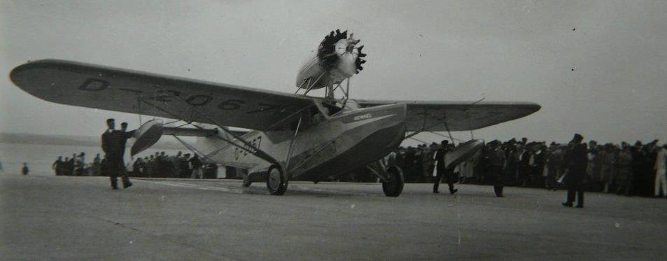
The Heinkel Amphibian (Flight 1931)
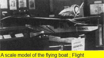
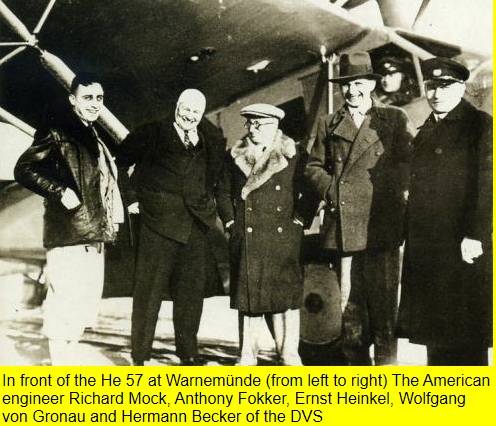
Dr. Ernst Heinkel is one of Germany's pioneers, and his name has. almost from the very earliest days, been associated mainly with the twin-float seaplane type of aircraft. In this connection it is perhaps worth while recalling thai before he formed his own company Dr. Heinkel was associated with the Hansa - Brandenburg lirm. whose machines were not unknown to British pilots during the war. In the main. Dr. Heinkel has remained faithful to his earlier ideals, but this has not prevented him from producing from time to time machines other than float- planes. He has produced some very good landplanes. and at Stockholm he showed an even later type, the H.E.57, which is a boat-type amphibian, designed for passenger-carrying. A model was published in Flight of December 12, 1930. At Stockholm the Heinkel H.E.57 Amphibian arrived from Warnemünde (where the Heinkel factories are situ- ated) piloted by Herr von Gronau. the German pilot who flew from Germany to New York, via Iceland and Green- land, on a Dornier Wal last year. The advantages of the amphibian were demonstrated in a small way at once, in that Herr Gronau was able to alight on the water outside the exhibition and taxi on to the slipway, and then, with wheels lowered, bring the machine right up on the shore just outside the main exhibition hangar.
The Heinkel H.E.57 is a strut-braced high-wing monoplane amphibian flying-boat of mixed construction. The hull is mainly built of Duralumin, while the monoplane
wing is largely of wood construction. Although of the two-stepped type, the hull of the H.E.57 differs in its lines very materially from the majority of British flying-boat hulls, even from those of the well known SARO boats with which the Heinkel may best be compared, because of its flat-sided hull. It is true that the Heinkel resembles other British boats in that it has two steps (the SARO boats having but one), but the general layout of the machine is more than that found in the boats of Mr. Knowler's design. The forward main step of the Heinkel is very like those found on all British flying-boot hulls, with a fairly pronounced vee. but the rear step is of totally different design, in that it resembles more the heel of a seaplane float, terminating in a vertical stern post which merges into the bottom of the rear. cocked-up portion of the main hull This vertical stern post carries a water rudder bv means of which the machine can be manoeuvred while taxying, and also forms a tail skid when the machine is used as a landplane.
Constructionally. the boat hull is fairly orthodox, the flat sides simplifying the construction of the frames and planking The bottom. from the bows to the rear step. have a pronounced vee, that ahead of the main step being a vee with curved planes while aft of the main step being a vee of the straight-lined type. Two watertight bulkheads divide the bout in three compartments, of which the one in the middle forms the cabin of the machine. In the forward compartment is stowed the marine gear, etc.. and this part is reached either through a hatch in the forward deck through a watertight door in the cabin bulkhead.
The rear part tne hull aft of the rearmost bulkhead. does not contain any load or equipment but a watertight door in the bulkhead gives access to it for purposes of inspecting controls and the interior of the boat hull. In the middle part of die interior of the hull is arranged the cabin and cockpit equipment, which consists of the usual chair seats with a gangway down the centre. There are seats for four passengers, and the two seats for the crew are placed side by side, and not separated from the
passenger cabin. In the roof there is a celluloid skylight, while in the sides of the cabin are rectangular glass windows. Around the sides and front of the forward part of the cabin are also glass windows of unsplinterable glass, the side windows being arranged to open and serving, in case of accident, as emergency exits for the crew and passengers. The cabin is reached through a hinged hatch in the deck, visible in one of our photographs. The land undercarriage consists of a tripod on each side, axle and radius rod being hinged to the sides of the hull, while the telescopic leg is attached near the top, at the point where the front wing spar fitting is mounted on the hull. The telescopic leg is of the oleo type, and raising the wheels is accomplished hydraulically by means of a hand-operated pump in the cockpit, "next to the pilot's seat.
The monoplane wing is of mixed construction, withwooden spars and duralumin ribs, covered with fabric The wing is braced by a pair of vee struts on each side, the lower end of the vee being attached to the sides of the hull approximately at waterline height. This position might be expected to make the boat slightly " dirty " during take-off. but, as we did not see the machine take off during our stay in Stockholm, we are unable to state from personal observation whether this surmise is correct or not. Wing-tip floats are attached at the points on the wing spars where the lift strut tittings occur, and, owing to the fact that the machine is a high-wing monoplane, the struts supporting the wing-tip floats are unusually long. Laterally, the wing-tip float supports are braced by nearly horizontal struts to the main wing bracing struts, and thence by vertical struts back to the wing spars.
A Pratt & Whitney " Wasp " engine is the standard power plant of the H.E.57, but, if desired, a " Hornet " can be substituted to give a better performance. The engine is mounted on struts above the wing, and drives a metal airscrew with blades adjustable for pitch. The airscrew blade tips pass very clese in front of the windscreen, and one would expect the beating of the air on the screen to cause considerable buffeting and noise in the pilot's compartment. Another disadvantage of arranging the engine as a tractor instead of as a pusher is that, when on the water, and manoeuvring up to a buoy or anchorage, the member of the crew who is working from the forward hatch has the airscrew fairly close behind him. It is true that the hatch cover is so designed as to rest at a considerable angle with the deck, and thus to afford some protection, but one cannot help thinking that the Heinkel amphibian, like a good many other machines, would be improved in many ways if the engine were turned around and made to drive a pusher airscrew. The main petrol tanks are placed in the wings, one on each side of the hull, and supply to the engine is by engine-driven petrol pumps. In the fairing behind the engine is, in addition to the oil tank, a small reserve petrol tank, separated from the engine by a fireproof bulkhead.
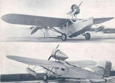
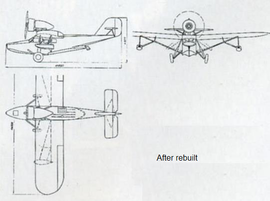
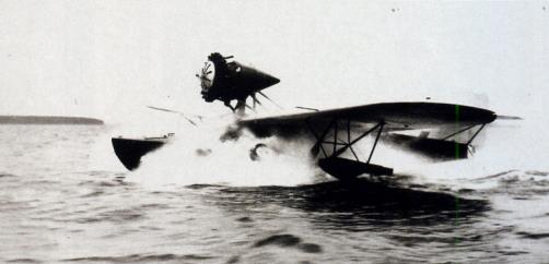
In parenthesis : The first design , later rebuilt with a tailskid
The aircraft was like a lead duck, too heavy and could not take off with the planned load That is why the machine became complete rebuilt. The boat shape was optimized in the water channel of the shipbuilding Research institute in Hamburg. It is externally changed with a slightly changed rear end with the removal of the tail wheel , which is now replaced by a tail skid behind the water rudder behind the step of the boat bottom
In principle, it was a completely new one airplane that in December 1930 went into testing again in the course of which was further tried The engine cowling and mounting of the exhaust system was changed , temporarily a ring cover mounted around the cylinder heads, the Tail assembly was modified several times and provided with small stabilization fins

| Type |
2 + 4/6 passenger carrying amphibium |
| Engine |
1 Pratt & Whitney "Wasp" |
| Dimensions |
Length 11,85 m ( 10,80 m) , height 3,76 m (3,55 m) with wheels 4,50 m (4,23 m), span 16,00 m , wing area 39,20 m2 , |
| Weights |
Empty 1820 kg (1550 kg), loaded 2600 kg / 2450 kg) , max. take off weight |
| Performance |
Max.. speed 185 km/h (195 km/h) at sea level , cruising speed , range , endurance , service ceiling , climb to 1000 m 8 min. (5 min.) landing speed 94 km/h (93 km/h) |
| Type |
Werk.Nr |
Registration |
History |
|
343 |
D-2027, D-OJAS |
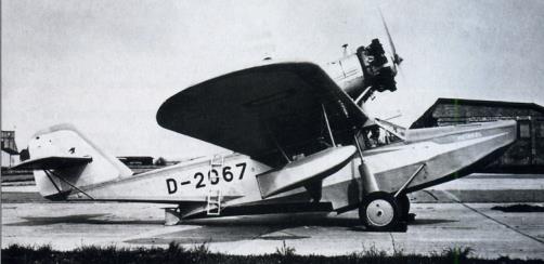
The He 57 received the approval in May 1931 registration D-2067 and took part in several air shows
at home and abroad , among others a few days at the Swedish Air Show "ILIS" in mid-May 1931 in Stockholm and then on May 31 in Copenhagen-Castrup.
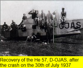
In the the end of April 1933 the Deutsche Verkehrsfliegerschule bought it for 126,000 Reich mark . The plane was assigned to DVS at Sylt and remained in use until 1937, from 1934 onwards with new registration
D-OJAS. After a crash landing on July 30, 1937 the HE 57 was scrapped: |


