The first Komets (Do C III Komet I) utilised the wing, tail, and even upper fuselage of the early Delphin versions, but replaced the lower fuselage and sponsons with a simple sheet-metal bottom that incorporated fixed tailskid undercarriage. The engine installation was also relocated from its peculiar position above the Delphin's nose to a conventional location in the Komet's fuselage nose. Accommodation was provided for a single pilot and four passengers. An improved version, the Do Komet II, was first flown on 9 October 1922 and was widely exported to countries including Colombia, Spain, Switzerland, and the Soviet Union.
| Type |
Prototype1 + 4 seat transport |
1 + 4 seat transport |
| Engine |
1 BMW III |
1 BMW IIIa |
| Dimensions |
Length 9.10 m, height 2.50 m, span 17.0 m, wing area 47.0 m2, cabin : length 2.0 m, height 1.6 m, width 1.2 m |
Length 9.50 m, height 2.75 m, span 17.0 m, wing area 50.0 m2, cabin : length 2.0 m, height 1.6 m, width 1.2 m |
| Weights |
Empty 1100 kg, fuel 144 kg, oil 20 kg, crew 80 kg, pay load 486 kg, flying weight 1830 kg |
Empty 1450 kg, fuel 220 kg (285 l + 20 l emergency tank), oil 20 kg, crew 80 kg, pay load 350 kg, flying weight 2120 kg |
| Performance |
Max. speed at sea level 170 km/h, cruising speed at sea level 130 km/h, climb 2.0 m/sec. at altitude 2000 m, service ceiling 5000 m, range 520 km, landing speed 80 km/h |
Max. speed at sea level 160 km/h, cruising speed at sea level 130 km/h, climb 1.3 m/sec. at altitude 2000 m, service ceiling 4000 m, range 800 km, landing speed 80 km/h |
| Type |
Werk.Nr |
Registration |
History |
|
3 (24) |
CH 49 |
First flight summer 1921, tested by the Swiss company Ad Astra in 1921 for a short period. Later rebuilt to Komet II standard |
|
5 (30) |
CH 50 |
Leased by Ad Astra from Dornier --- 1921 - June 1922.. Rebuilt to Komet II standard |
|
8 (45) |
|
Rebuilt to Komet II standard |
A NEW GERMAN ALL-METAL MACHINE (From Flight)
The Dornier C3, 185 B.M.W. Engine
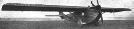
IN our issue of December 16, 1920, we published a description of the Zeppelin Dornier machines built at Lindau. This series of " Milestones " included the latest monoplane flying boat produced at the Zeppelin works at Lindau, and it was mentioned that the products of Herr Claude Dornier, chief designer of the firm, were well worth watching. At the time we also promised to keep our readers informed of any new developments that might come along. An opportunity of keeping this promise has now occurred, the Zeppelin factory having produced a new and highly interesting monoplane to the'designs of Herr Dornier. There is, we believe, quite a keen competition going on between the Zeppelin works at Lindau and those at Staaken (the chief designer at the latter factor}' being Herr Rohrbach) to see who can first produce a really successful commercial machine. The Zeppelin Staaken lour-engined monoplane was described and illustrated in our issue of March 17, when we also reproduced the first photograph to be published in this country of a wind channel model of the new twin-engined Staaken monoplane which is now under construction. While Herr Rohrbach seems to devote his attentions to fairly large machines, Herr Dornier at Lindau now appears to specialise more in the smaller, single-engined type, the latest of his productions being the C3 monoplane illustrated herewith. For the illustrations and data relating to this machine we are indebted to the German aviation journal Illustrierte Flug-Woche.
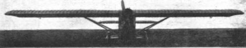
The D0.C3, as the new machine is styled, is an all-metal monoplane with fairly thick wing section. A peculiarity, which the D0.C3 shares with the previous monoplane flying boat, is that, although the wing is of deep section, it is tapered neither in chord nor in depth: The consequence is that it has not, apparently, been found possible to make it a true cantilver wing, it having a pair 01 struts on each side to support it. Aerodynamically it is an advantage to taper the wing, as a fairly high L/D ratio can then be obtained while still retaining a fairly high maximum lift. Such a tapered wing, how- ever, is more expensive to build thin is a parallel one, and possibly it is this fact which has influenced Jierr Dornier in his choice of wing form.
Constructionally the wing of the D0.C3 is interesting on account of the fact that it is built of metal throughout. The framework of the wing is in steel, while the covering is stated to be sheet Duralumin. Although this covering does undoubtedly strengthen the wing, no account of this has been taken in stressing the machine, and the covering is merely intended to act as a means of maintaining the exact curvature of the wing, it having been found that in high-lift wings quite minute changes in curvature may sometimes have extraordinarily great influence upon the aerodynamic properties.
The wing is without dihedral, and is built in one complete unit from tip to tip, the centre of the wing resting on the top of the cabin. Bracing is by means of four streamline section steel tubes, two on each side, running to the lower longerons of the fuselage. Owing to the considerable depth of the body, the angle of the bracing tubes is very good. Small ailerons are fitted near the tips, and the cranks, etc., for operating the ailerons are buried inside the wing.
The tail plane is also of approximately rectangular plan form, and is a cantilever structure of similar construction to that of the main plane. The elevator is divided and unbalanced. The rudder, on the other hand, has a balance portion projecting forward above the fixed vertical fin. Tail planes and control surfaces are also covered with aluminium alloy. *
The fuselage is a steel structure covered with Duralumin, and is very deep in front, the engine being mounted fairly high, and the centre of thrust only slightly below the level of the wing. The cabin is aft of the engine, from which it is separated by a fireproof bulkhead. Seating accommodation is provided for six passengers, who enter the cabin through a door in the starboard side, direct from the ground, without needing any-steps, the floor of the fuselage being exceptionally low over the ground. Windows are provided in each side of the cabin, and as the wing is above the cabin the passengers obtain an unobstructed view of the ground. It is pointed out that as the machine is intended to a great extent for use over the beautiful scenery of Switzerland,' this is a great advantage. Great attention has been paid to the prevention of fire on board, all fuel tanks being situated in the wings, outside the body.
The pilot is placed aft of the cabin, his cockpit being located just aft of the trailing edge of the wing. Here, it is claimed, he obtains a very good view, as he is on a level with the trailing edge, and can thus look over or under the wing at will. Perhaps one of the most interesting features of the D0.C3 is the undercarriage. This, it will be seen from the accompanying illustrations, is in the form of two short wing roots totally enclosing the wheel axle, with a disc wheel at each end. It would be difficult to imagine a simpler undercarriage, and although the structure is probably fairly heavy, as it almost necessarily must be in order to take the loads from the wheels at the ends of the two short cantilever wing roots, the resistance should be quite small.
The engine fitted to this machine is a 185 h.p. B.M.W. over-dimensioned, high-compression six-cylindered motor, which is one of the best examples of modern German engine design. It is very economical in fuel, even when running throttled, while the effect of the design is to enable the engine to maintain its full power up to a height of about 10,000 ft. The normal power for. cruising is 200 h.p. at 1,400 r.p.m., while for short periods, such as for getting off, the engine can be revved up to 1,500 r.p.m., when it develops about 240 h.p. As the machine is fairly lightly loaded per square foot of wing surface, she is said to get off well and to have a good climb, while requiring only a short run for getting off.
The following are the main data relating to the D0.C3 :
Span, 55 ft. 9 ins. ; length o.a., 29 ft. 10 ins. j height, 8 ft. 3 ins. ; chord, 9 ft. 10 ins. ; wing area, 506 sq. ft. ; weight, empty, 2,420 lbs. ; useful load, 1,600 lbs. ; weight, fully loaded, 4,oio lbs. ; load per sq. ft., 7.95 lbs. ; load per h.p. (on 200 h.p. basis), 20 lbs. ; maximum speed, 105 m.p.h. ; cruising speec1, 80 m.p.h. ; ceiling, 16,500 ft. ; fuel consumption, .45 lb./h.p./hour ; oil consumption, .022 lb./h.p./hour ; range, about 400 miles
Kennzeichen D-528,
Steel spar knot, both of which are in D, connected by uprights oblique U-shaped, forming a Warren beam.


