By Cap. Rudolph Jahn
Deutsche Lufthansa
GERMANY'S interest in Trans-Atlantic flying which culmi-
nated in the survey flights of the two Dornier flying boats
Zephir and Aeolus late this summer dates back many years.
In 1929 Deutsche Lufthansa A.G. in- augurated a ship to shore ser- vice for mail in conjunction with the North
German Lloyd line ships Bremen and Europa. No trans-Atlantic service was undertaken at that time, but the plan
was to save on mail schedules by catapulting planes from the steamers when about 600 miles off the coast
when approaching the United States or Great Britain. Single-engined twin-float Junkers seaplanes with a crew
of two pilots were used. The average saving in time amounted to about 50 hours on mail deliveries. Accelerated
mail service of this type was carried on regularly for eight years during the summer months only.
The experience with the mail service proved so satis-factory, and so much was learned about catapulting
that when flight operations across the South Atlantic were being studied, the use of a catapult for launching the
larger flying boats was considered the most practicaldevice to adopt. The Heinkel Works (who had done much
of the early work with catapults) designed equipment suitable for launching flying boats up to a total gross
weight of 15 tons.
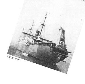
After exhaustive tests ashore it was decided to install the equipment on board a ship. A small freighter, the
Westphalen, was secured and her upper works rebuilt to accommodate a catapult forward (of the same type
to be described later for the Schwabenland) and a crane for hoisting flying boats aboard was installed aft.
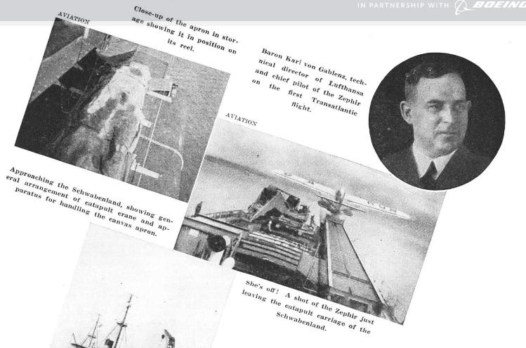
Most novel part of the equipment was a large canvas apron which could be trailed astern and which made
available a sort of ramp onto which flying boats could be taxied before being hoisted on board. Without the
apron it would be impractical to try to secure the boat to the crane in any sort of sea. The apron established a
reasonably fixed relationship between the crane and the flying boat and enabled it to be taken on board
without damage. In those days the range of the Dornier Wals which were being used for the service was not
great enough to fly the whole stretch across the South Atlantic, and the Westphalen was stationed halfway
between Bathurst in West Africa and Natal in Brazil. The procedure was to land the flying boat alongside, take
it on board, refuel it and catapult it to resume its flight. With the advent of the so-called 10-ton Wal the range
was so increased that the crossing could be made without intermediate landing. The Westphalen was accord-
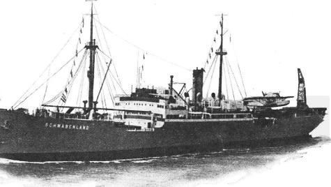
ingly withdrawn from mid-Atlantic and a newer catapult ship, the Schwabenland, was acquired. By stationing
one ship on one side of the Atlantic and one on the other it was possible to catapult the 10-ton Wal into the air
with sufficient fuel for the crossing. The time, which under the older system was five to six days from Berlin to
Natal, was thus speeded up to an average of three days. Actually, at the present time the schedules are
running close to 2,5 davs.
When the North Atlantic services were studied, it was decided to use a similar arrangement, but the range of
the 10-ton Wal was not sufficient to cover the longest over-water jump. A new machine had to be designed
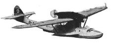
for this work which is now known as the Do-18. The Zephir and the Aeolus are of this type. Although the Do-18
traces its ancestry back to the original Dornier Wal which carried Amundsen over the North Pole, the new
model shows many aerodynamic and structural refinements. It was not intended for passenger service but for
carrying mail and freight over long ranges after catapulting. The ship is a high-wing monoplane of all metal
construction, stabilized on the water by sea wings of the type familiar to American
readers on the Martin Model 130 Clipper. The wingsare semi-cantilevered,
strut braced to the sea wings. Be- tween the hull and the wing is a stream-
lined turret through which the crew can reach the interior of the engine
nacelles. The wing is very efficient both structurally and aerodynamically.
It is tapered in thickness and in plan form, with the thickest portion at the
points where the bracing struts are connected. Each panel tapers both
toward the center section and toward the tips. The wing carries a flap
below the trailing edge which runs practically the full length of the span
(except across the center section). Each auxiliary wing is divided into two
sections, the inner of which function only as a flap, the outer section
functioning both as flap and as aileron.
The hull is divided into a number of compartments fore and aft. In the
extreme nose is housed all the marine equipment including anchors, tow-
lines, etc. Next comes the pilot's cockpit. Particular attention has been
paid to visibility for both pilots. The transparent cockpit covers are hinged
to provide entrance to the compartment. The instrument board is fitted with
all the necessary navigation and engine control instruments. Its layout is
simple and efficient. Dual controls are fitted.immediately behind the
pilot's cockpit, accessible through a door in the bulkhead, is the radio and
navigation room. Equipment for two-way communication on long and short
waves is installed. Radio direction-finding equipment is also on board.
As may be seen in some of the photographs, a rotatable loop antenna is
mounted well toward the tail, remote controlled from the operator's position.
On the port side, opposite the radio operator is the navigator's table with
convenient map cases, instruments, etc.
Behind the navigating room is a compartment which holds miscellaneous
mechanical equipment including an oil tank, an emergency fuel pump,
storage batteries, cooling water storage tank, bilge pumps, etc. A small
work bench with hand tools for emergency repairs is also installed. Next
aft is a battery of four aluminum fuel tanks having a capacity of about 700
litres (185 gallons), each. These tanks are removable through a screw-
down hatch on the deck. Fuel feeding from the four tanks is pumped into a
collecting tank and from there to each of the two engines.
Immediately behind the fuel section is a compartment for mail and freight.
The extreme after part of the hull is empty in flight. It is accessible
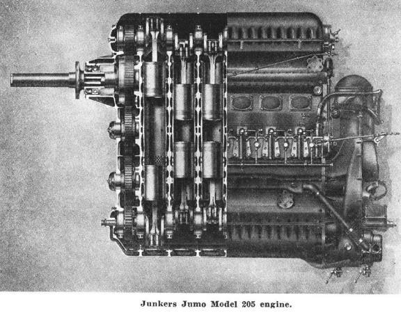
for inspection through a door in the rear bulkhead. The two Junkers
Jumo 5 diesel engines are installed in tandem in a well faired nacelle
which forms the center section of the wing. The cowlings are easily
removable, however, so that the engines are completely accessible for maintenance work. The fairing panels along the side of the front engine are hinged and may be let down to serve as platforms on which mechanics may stand. The front engine drives a tractor propeller while the rear one drives a pusher through an extended shaft. Three-bladed metal propellers are fitted to both engines. The forward profiler is of the controllable pitch type. The rear propeller is fixed pitch. Two radiators for cooling water arc arranged one above the other in the leading edge of the turret. They are fitted with controllable shutters to control the cooling. This arrangement gives good cooling possibilities and at the same time low aerodynamic resistance. Two reservoirs for the cooling water are mounted high in the nacelles. When necessary they can be replenished from the water storage tank in the hull by means of a semi-
rotary hand pump. Tubular radiators for cooling the lubricating oil are hung in the air stream under the wing outboard from the turret. For summer operations in the tropics, additional radiation for the cooling water has been provided by means of fiat-type radiators suspended below the wing surfaces outboard from the tubular oil radiators described above.
Of particular interest are the power plants themselves, the Jumo 5. Development of heavy oil engines of this type was begun by the Junkers Company as far back as 1924 when Professor Junkers built the first experimental aero diesel for test bench purposes only, but on the same principle as the present Jumo 5. After a long research the first aircraft diesel turned out was fitted to several Junkers F-24 airplanes for experimental work. These engines proved
so successful that Lufthansa installed them in the four-
engine transports of their fleet, the Junkers G-38. A somewhat smaller engine which embodied all
the experience gained with the Jumo 4 was built, the present Jumo 5.
These engines are of the compression ignition type, burning a special oil and developing 550 hp.
each. The arrangement is six cylinders in line, but each cylinder is double-acting, containing two
pistons each of which drives a separate crankshaft. The two crankshafts are geared to a common
propeller shaft. These engines operate on the well known diesel principle in which air is compressed
in the cylinders and fuel is injected into the heated air at the proper instant. There are, therefore, no
ignition systems, no carburetors and no valves of the type used in other aircraft engines. The fuel
consumption of these engines is extremely low. [Jane's "All the World's Aircraft-1935" gives a fuel
consumption of .353 to .375 lb. per hp. at normal output; and .375 to .396 lb. per hp. at maximum
output.-Ed.]
So much for the airplanes and their engines. Another interesting item of mechanical equipment in
the Atlantic operation is the catapult as installed on the Schwabenland. It is essentially of the same
type as originally mounted on the Westphalen but with improvements. Where the catapult equip-
ment on the Westphalen was forward, however, on the Schwabenland it is aft. The flying boats are
launched from the stern of the ship. During catapulting operations, enough sternway is kept on the
steamer to maintain the heading into the wind at all times. As can be seen in some of the
accompanying photographs, the catapult is mounted on the port side of the ship with the crane and
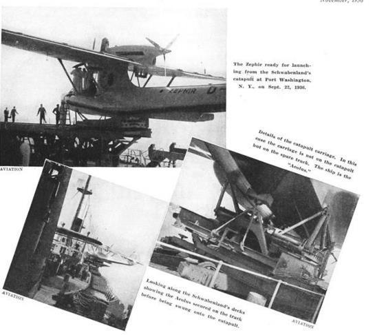
the track for handling a spare airplane to starboard. The reel and arrangement for handling the sea
apron is located at the stern below the catapult. The catapult proper consists of two
long steel rails (about 100 ft. in the clear) on which is mounted a car, or rather a sledge. The latter is
not mounted on wheels but slides directly on the top of the rails.
The carriage is pulled along the cata- pult by two flexible steel cables each of which is about 2 in. in
diameter. They are kept well lubricated, both for protection against corrosion and for flexibility^
The cables pass over a large pulley near the discharge end of the catapult and from thence under
the structure to the operating cylinders located about the center of the framework. Here the
cables pass back and forth over a system of sheaves arranged very much like the ordinary block and tackle. One set of sheaves is stationary and the other is mounted on a slide which in turn is connected to the piston of a large air cylinder. By forcing the two sets of sheaves apart by the action of the air cylinder the relative motion of the piston is compounded so that for every foot of travel of the piston, 6 ft. of travel on the cata-pult carriage is obtained.
Compressed air for operating the launching cylinder is stored in large tanks immediately below the cylinder. Pressures between 1,200 and 1,400 lb. per sq.in. are employed. Take-off speed is varied according to the speed of surface winds by varying the pressure of the compressed air. With the plane on the carriage in the take-off position the two engines are warmed up and are finally run up to full throttle. After the crew have gotten themselves properly braced in their places, the pilot pushes a small button under his right thumb on the steering wheel which flashes a red light at the firing station. The catapult engineer then throws a lever opening the valve connecting the compressed air container and the cylinder, the piston forces the two sets of sheaves apart, and the carriage is accelerated along the catapult. In one and one-half seconds the boat is accelerated from a standstill to about 80 m.p.h. Since this is above the minimum flying- speed for the boat, it is able to climb directly after having left the catapult. There is no loss of altitude. Actually the boat leaves the carriage somewhat before the end of the catapult is reached. Then the problem is to stop the carriage. This requires considerable braking. The structural steel cradle must be decelerated from 80 m.p.h. to a standstill in about 15 ft. Two sets of brakes act. The first consists of a knifelike vertical plate mounted on the underpart of the carriage which slides between pairs of stationary steel shoes under the end of the track. The shoe plates are pressed together horizontally by air cylinders. The pressure in the brake cylinders is the same as that used for the firing cylinder. The other braking action comes from the launching cables. Since the pulley at the discharge end of the catapult is not at the extreme end, the carriage over-runs it and the cable Since the pulley at the discharge end of the catapult is not at the extreme end, the carriage over-runs it and the cable then acts in a reverse direction tending to stop it. During this part of the cycle the compressed air cylinder acts as a sort of dashpot to retard the carriage with minimum shock. Although the accelerations acting during catapulting may run as high as 2 to 2,5 g., there arc no noticeable ill effects on the crew in as many as five or six branchings a day.