| Type |
A Two seat trainer |
B Two seat trainer |
| Engine |
1 Argus As 10C |
1 Argus As 410A-1 |
| Dimensions |
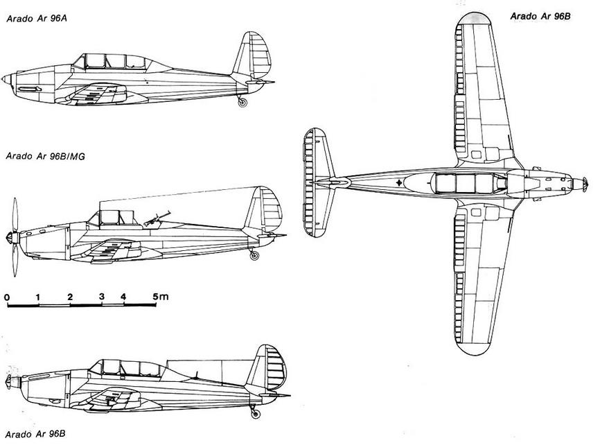
Length 8,35 m, height 2,64 m, span 10,96 m, wing area 17,10 m2 |
Length 9,13 m, height 2,59 m, span 10,96 m, wing area 17,30 m2 |
| Weights |
Empty 1187 kg , take-off weight 1500 kg |
Empty 1295 kg, take-off weight 1700 -1800 kg |
| Performance |
Max. speed 275 km/h, service ceiling 5500 m, range 950 km |
Max.speed 310 km/h, service ceiling 7100 m, range 990 km |
| Production figures up to 1945 |
| Version |
Arado |
AGO |
Avia |
Letov |
Total |
Construction Period |
| Prototypes |
4 |
|
|
|
4 |
1937- 1938 |
| A-0 |
6 |
|
|
|
6 |
Including 3 delivered on 1 April 1939. Werk.Nr. 2879-2884 |
| A |
23 |
69 |
|
|
92 |
Mid 1939 - May 1940 |
| B-0 |
2 |
|
|
|
2 |
1940 |
| B-1 |
144 |
223 |
997 |
17 |
1381 |
July 1940 - April 1944 |
| B-3 |
|
|
210 |
|
210 |
1941 - 1943 |
| B-6 |
|
|
100 |
|
100 |
July 1943 - January 1944 |
| B-7 |
|
|
518 |
378 |
896 |
May 1944 - March 1945 |
| B-7/B-8 |
|
|
|
81 |
81 |
December 1944 - March 1945 |
| B-8 |
|
|
|
74 |
74 |
June 1944 - January 1945 |
| Sales series |
45 |
|
|
|
|
1939 - 1940 |
| Totals |
224 |
292 |
1825 |
550 |
2891 |
It is estimated thät close to 3400 planes were made |
| A-0 |
|
| A-1 |
|
| B-0 |
|
| B-1 |
|
| B-2 |
Fighter training Equipped with guncamera , radio and a MG 17 machine gun |
| B-3 |
|
| B-4 |
|
| B-5 |
|
| B-6 |
|
| B-7 |
|
| B-8 |
|
| B-10 |
|
| C |
|
| Export |
|
| Export |
| Version |
Country |
Number |
| |
Slovakia |
|
| |
Romania |
|
| |
Hungary |
|
| |
Bulgaria |
|
Without doubt the most important advanced trainer produced for the
LuftwafTe was the Arado Ar 96. Extremely advanced for its time, the Ar
96 was designed in 1938 by Dipl Ing Walter Blumc. chief designer of
Arado Flugzeugwerke GmbH. It was a neat cantilever low wing mono
plane built of light metal throughout with duralumin skin. The pupil and
instructor were seated in tandem beneath an elongated and extensively
glazed canopy. The fuselage was an oval section monocoque struc
ture built in two halves and the mainwheels retracted into the wing centre
section. The tail assembly was of typical Arado design with a tall fin
and rudder of narrow chord and the tailplane mounted at the extreme
rear of the fuselage.
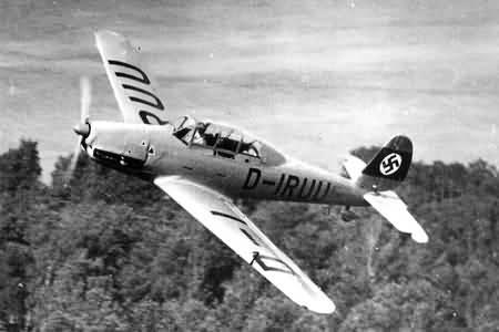
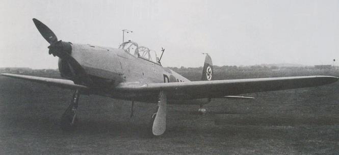
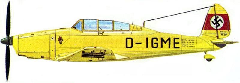
The prototype, the Ar 96 V I D-IRUU, powered by a 240 hp Argus As
IOC eight cylinder inverted vee air cooled engine, flew for the first time in
1938. As originally flown, the Ar 96 V I had an outward retracting under
carriage, but this was replaced by the inward retracting type subsequently
adopted for all production aircraft. The wide track undercarriage was
considered to be much more suitable for the rough landings associated
with fledgling pilots.
The Ar 96 proved so successful that the RLM placed a large order for
the machine in 1940. A small batch of Ar 96A 1 aircraft had been
completed in 1939. these being powered, like the first prototype, by the
240 hp Argus As 10C engine. It was foreseen that the aircraft would
provide the Luftwaffe's training schools with an excellent intermediate step
between the standard initial trainers such as the Ar 66. Fw 44. Go 145 and
He 72 biplanes and the advanced fighter monoplanes which were then in
service.
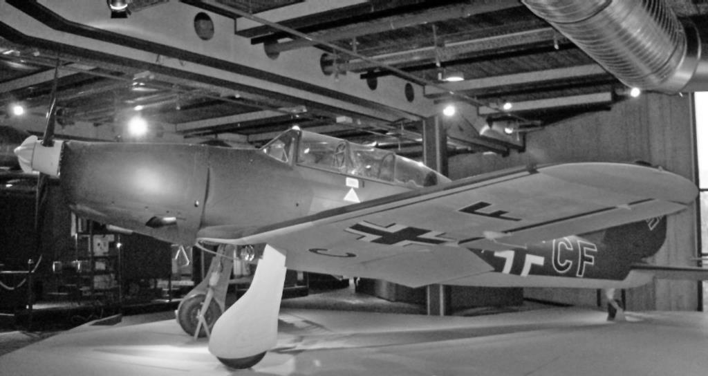
The main production series was the Ar 96B which differed in being
powered by a 465 hp Argus As 410A I twelve cylinder inverted vee air
cooled engine driving a two blade metal airscrew with an Argus automatic
pitch change spinner. The Ar 96B also had a longer fuselage to accommo
date more fuel. The first production model was the Ar 96B I unarmed
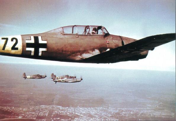
pilot trainer. The Ar 96B-2 carried a 7-9 mm MG 17 machine gun. for
gunnery training, above the engine cowling and offset to starboard. A
further five B series aircraft have been reported including the Ar 96B-5
pilot gunnery trainer and the B 7 which could carry bombs for the training
of ground attack and dive bomber pilots. Other aircraft were modified for
night and blind flying^ communications and navigational training, and at
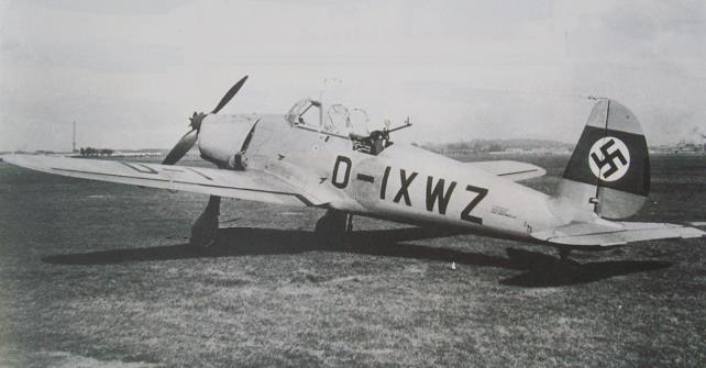
least one. D IXWZ, carried a 7-9 mm MG 15 machine gun in the rear of
the cockpit for the training of air gunners.
Despite the success of the Ar 96. relatively few were built by the Arado
company. Until mid 194 I. the Ago Flugzeugwerke (a Junkers subsidiary)
built most aircraft, but then, the Czechoslovak Avia company took over
series production. The Letov company of Prague joined the Ar 96 pro
gramme in 1944 and by the end of the war no less than 1 1.546 aircraft had
been completed.
The Ar 96C. of which only a pre-production batch was built, was
powered by a 480 hp Argus As 410C engine and had a small window in
the floor of the cockpit for bomb aiming practice. A development of the Ar
96B was the Ar 296 project to be pqwercd by a 600 hp Argus As 41 1
twelve cylinder inverted vee air-cooled engine. This was abandoned in
favour of the Ar 396 (see page 54) designed to use the minimum of
strategically important materials. After the war the Ar 96B remained in
production in Czechoslovakia until 1948 under the designation C.2B I.
The Ar 96B formed the main equipment of the Jagdschulgeschwader
(fighter-training wings) of which there were eventually thirteen, designated
JG lOltoJG HOandJG 114toJG 1 16. The aircraft also served with the
training and replacement fighter units (EJG), the pilot training schools
(FFS A/B Schulen) and the officer cadet schools (LKS).
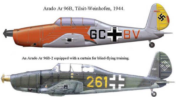
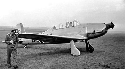
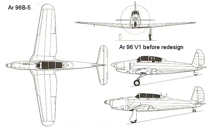
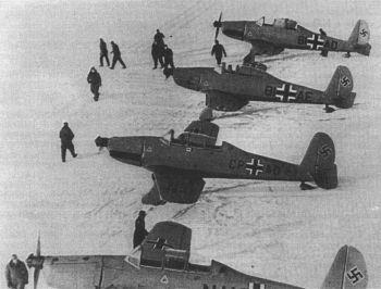
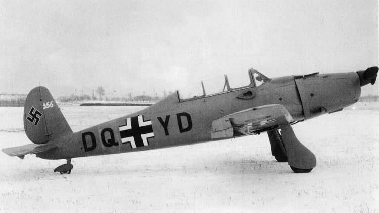
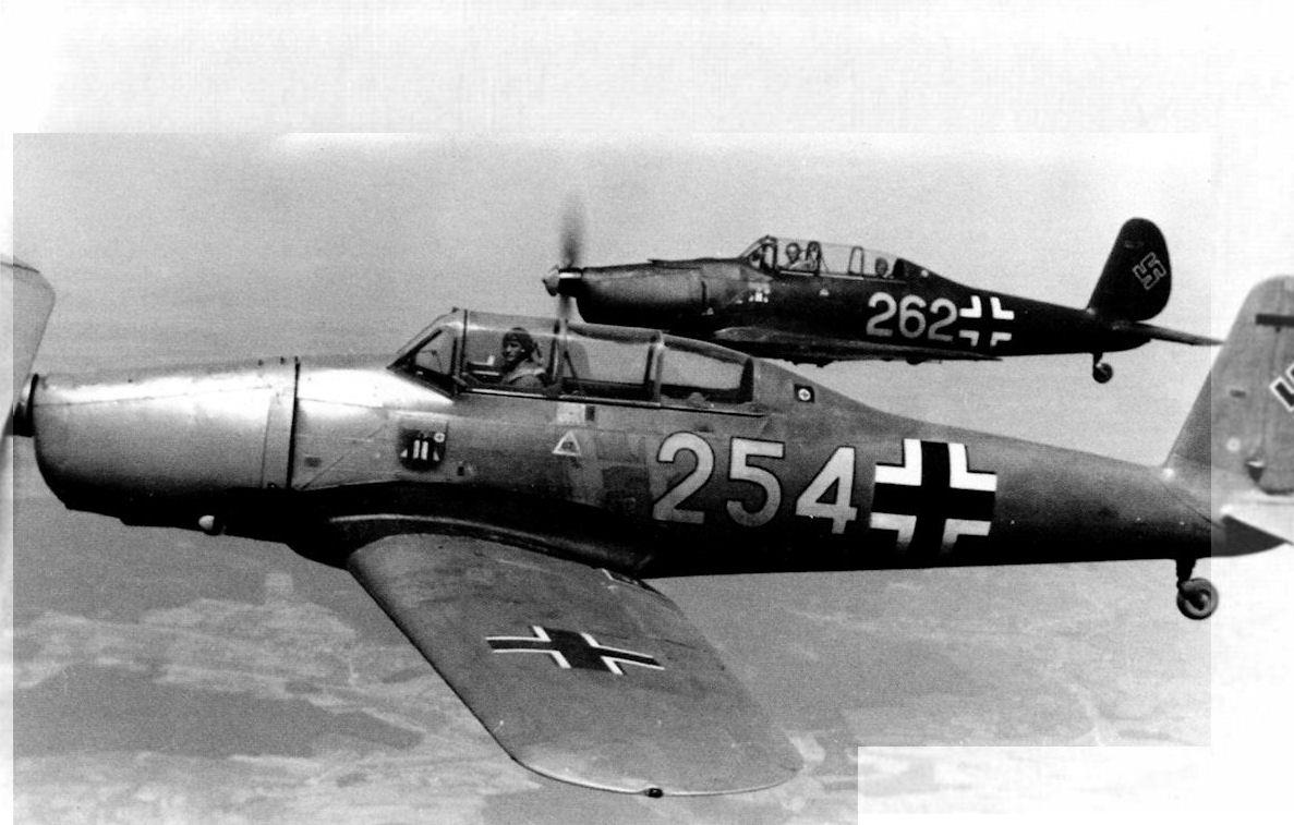
Arado Ar 96 B.
Arado Ar 96 A (vgl. Typenbeschr. „Flugsport" 1937 S. 263 und 306) und Arado Ar 96 B zeigen wesentliche Unterschiede im Verwendungszweck, in den Motoren und in
der Konstruktion. Ar 96 A wird mit dem 240-PS-Argus-Motor As 10 C ausgerüstet, dient als Fortbildungsschulflugzeug für den Flugzeugführer, ferner zur Uebung für
den Beobachter und zur Ausbildung im Kunst-, Nacht-und Blindflug. Ar 96 B dagegen ist ein Mehrzwecke-Uebungsflug-zeug, das auch als leichtes Kampfflugzeug
durch seine Bewaffnung und Ausrüstung, seine Eigenschaften und Leistungen einsatzfähig ist. Als Uebungsmaschine dient sie neben den bereits bei der Ar 96 A
aufgeführten Verwendungszwecken der Ausbildung von Führer und Beobachter im MQ-Schießen und Bombenwerfen, ferner in der Photographie und Telegraphie. Ar 96
B ist mit dem 360/450-PS-Argus-Motor As 410 A ausgerüstet. Ihre Leistungen liegen wesentlich über denen der Ar 96 A.
Das Tiefdecker-Tragwerk aus einem, ohne lösbare Trennstelle hergestellten, freitragenden Trapezflügel mit 6° V-Form wird mittels vier Kugelgelenken unter dem Rumpf
angeschlossen. Die Anschlußbeschläge gestatten einen Ausgleich bei Winkel- und Längenänderungen infolge Durchbiegung des Flügels und gewähren dessen einfache
Au stau s ch b arkeit.
Der statische Aufbau des allseitig mit Blech beplankten Flügels besteht aus zwei I-Holmen mit kräftigen Verbundrippen. Handlöcher in der Außenhaut ermöglichen
Kontrollen und Reparatur arbeiten.
Am Flügel sind automatische Handley-Page-Schlitzflügel eingebaut, in der Flügelnase das innen hochklappbare Verschwindfahrwerk. Je ein kräftiger Aufbockbeschlag
mit Oesen zum Festzurren der Maschine ist zwischen den Rippen 7 und 8 vorgesehen.
Rumpf, Qanz-Metall, besitzt durchweg ovalen Querschnitt, die Rumpfhaut wird aus längslaufenden Profil- und Qlattbahnen gebildet. In der linken Rumpfwand zwei
Aufstiege und zwei Handgriffe; besondere Beschläge zum Aufbocken. Führer- und Beob achter räum sind mit Schiebehauben aus Plexiglas verkleidet, die durch eine
Klemmvorrichtung in jeder Stellung festgestellt werden können. Dies ermöglicht ein unbehindertes Ein- und Aussteigen und gute Lüftungsmöglichkeit, für die außerdem
noch eine regulierbare Belüftung vorgesehen ist. Vorderer Fußbodenabschnitt des Beob achter raumes kann entfernt und durch eine Plexiglasscheibe ersetzt werden, um
beim Einbau von Reihenbildgerät oder Bomben ziel Vorrichtung eine gute Durchsicht zu gewähren.
Führer- und Beobachtersitz senkrecht verstellbar, Gewicht der Insassen durch Gummikabel ausgeglichen. Sitze sind für Mitnahme eines Sitzkissenfallschirmes
eingerichtet und
mit verstellbaren Bauch- und Schultergurten versehen. Hinter dem zweiten Sitz Gepäckraum. Knüppel-Doppelsteuerung:, Uebertragung der einzelnen Steuerbewegungen durch Hebel, Stoßstangen und Gewindedrähte; letztere sind für die Höhen Steuerung
doppelt verlegt. Der im hinteren Sitzraum befindliche Teil der Steuerung kann ausgebaut werden. Seiten Steuerung des Vordersitzes ist in Fußdrehhebel-Bauart, die des
Rücksitzes in getrennter Fußpendelhebel-Bauart ausgeführt. Beide lassen sich in ihrer Lage zum Führersitz während des Fluges ver-steilen. Verstellung erfolgt im Vordersitz durch Ziehen eines ! Knopfes am Hilfsgerätebrett, im Rücksitz durch Umlegen eines I kleinen Hebels an den Pendelhebeln
selbst. Am Seitensteuerfußhebel des Vordersitzes befinden sich die Bremspumpen für die Bremsanlage des Fahrwerkes, die mit den Fußspitzen betätigt werden. Alle
Steuerbewegungen sind durch einstellbare Ausschläge begrenzt und leichtgängig. Das Flettnerruder am Höhenruder wird durch einen im Vordersitz links angebrachten
Schiebeknopf betätigt, dessen Bewegungen sich durch Stoßstange, Hebel und Stahldrähte übertragen.
Ein im Vordersitz angebrachter Schalthebel betätigt die Landeklappen auf hydraulischem Wege. An ihm ist die Startstellung besonders gekennzeichnet, ebenso zeigt
eine mechanische Vorrichtung den jeweiligen Stand der Landeklappen an. Bei ausgefahrener Landeklappe und Vollgasgeben geht die Landeklappe infolge Kuppelung
zwischen Landejklappenbedien- und Gashebel automatisch auf günstigste Startstellung zurück. Eine Kuppelung der Querruder mit den Landeklappen bewirkt, daß bei
einem Landeklappenausschlag von 45° die Querruder-Null-Lage auf + 13° gebracht wird, wobei noch der volle Ruderausschlag gegeben werden kann.
Die im Außenflügel eingebauten Spaltflügel sind im eingefahrenen Zustand verriegelbar und können durch Umlegen eines Kipphebels am Hilfsgerätebrett entriegelt
werden.
Die Hebel für Gas- und Gemischregelung sind an der linken Rumpfwand angebracht. Bei der Rücknahme des Gashebels wird der Gemischhebel mit zurückgenommen.
Der Motor kann sowohl mit Handandreh Vorrichtung-als auch mit Druckluft angelassen werden. Für letzteres ist eine Schnellkuppelung im Rumpf hinter dem
Brandschott vorgesehen, die von außen durch den Radkasten zugänglich ist. Kleiner Kraftstoffbehälter aus Aluminiumblech, Fassungsvermögen 205 1, ist unter dem
Fußboden des ersten Sitzes eingebaut und mit Gummizwischenlagen auf Rippen gelagert. Befestigung durch Spannbänder in den Holmen des Tragflügelmittelstückes.
Bei Grundüberholungen ist der Ausbau nach Lösen der 4 Aufhängebolzen möglich. Auffüllen erfolgt durch einen Außenbordanschluß auf der linken Rumpfseite. Auf der
Behälterunterseite befindet sich zum Entleeren ein Ablaßventil. Schmierstoffb eh älter aus Stahlblech, 18 1, liegt auf der vorderen Seite des Brandschotts, auf der linken
Seite mit einer Einfüllverschraubung, auf der unteren Seite mit einem Ablaßventil versehen. Aus puff stutzen sind rechts und links jeweils in einen gemeinsamen seitlich
angebrachten, nach außen gezogenen Auspuffs ammler geführt, um die beiden Sitze vom Strom der Auspuffgase freizuhalten.
Höhenflosse, Ganz-Metall, ist in drei Punkten gelagert, Anstellung am Boden verstellbar. Das gewichtlich und aerodynamisch ausgeglichene Höhenruder besteht aus
einem Leichtmetallgerüst mit Stoffbehäutung. Seine steuerbare Hinterkante ermöglicht ein Austrimmen des Flugzeuges im Fluge.
Seitenflosse, Ganz-Metall, ist in drei Punkten am Rumpf befestigt. Der Spalt zwischen ihr und dem Rumpf ist durch eine stromlinienförmige Blechverkleidung abgedeckt.
Seitenruder mit am Boden verstellbarer Ruderkante aus Leichtmetallgerüst mit Stoffbespannung ist gewichtlich und aerodynamisch ausgeglichen.
Querruder aus Leichtmetall mit Stoff bespannung gewichtlich und aerodynamisch ausgeglichen. Landeklappen Leichtmetallgerippe mit Stoff bespannt.
Verschwindfahrwerk wird durch eine hydraulische Hubvorrichtung über den Motor, bei Aussetzen des Motors mittels einer Handpumpe aus- und eingefahren, wobei die
Fahrgestell bei ne seitlich nach innen hoch geschwenkt werden. Endstellungen des Fahrgestelles werden durch eine elektrische Signalanlage und eine mechanische
Anzeigevorrichtung angezeigt. Ein Warnsignal (Hupe) ertönt, wenn bei nicht ausgefahrenem Fahrgestell der Gashebel zurückgenommen wird, solange, bis durch
Drücken eines Knopfes am Knüppelgriff Abstellung erfolgt. Bei Freilassen des Knopfes ertönt die Hube sofort wieder, und zwar solange, bis das Fahrgestell ausgefahren
ist. Die Federung der Fahrgestell bei ne besteht aus einer Druckgummisäule mit einem Oeldämpfungszylinder. Die Bremsräder (Bauart Argus) mit Hochleistungsreifen
580X165 werden hydraulisch von den Fußhebeln der vorderen Seiten Steuerung aus betätigt.
Spannweite 11 m, Länge 9,13 m, Höhe 2,64 m, Flügelfläche 17,10 m2. Motor Argus As 410 A, Startleistung 450 PS, Leistung in Volldruckhöhe (3000 U/min) 360 PS,
Volldruckhöhe 3000 m, Kraftstoffverbrauch (n = 0,85 nmax) 200 g/PS/h. Zweiflügelige Verstell-Luftschraube (Automat), Durchm. max. 2,7 m.
Leergewicht 1220 kg, Gesamtlast 530 kg, Fluggewicht 1750 kg, Kraftstoff 183 kg, Schmierstoff 21 kg, Flächenbel. 102 kg/m2, Lei-stungsbel. 4,86 kg/PS.
HÖchstgeschw. am Boden 310 km/h, in 3000 m Höhe 340 km/h, Reisegeschw. (n = 0,85 nmax) am Boden 255 km/h, in 3000 m 275 km/h, Landegschw. 103 km/h,
Flugdauer 4 h, Reichweite 1100 km. Steigzeit auf 1000 m 2,5 min, auf 2000 m 5 min, auf 3000 m 7,5 min, auf 4000 m 10,3 min. Dienstgipfelhöhe 7200 m.